|
|
|
|
Thread OP
|
Discussion
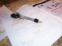
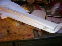
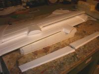
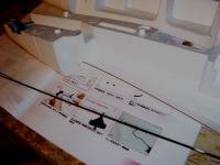
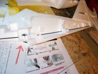
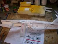
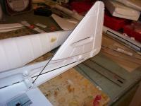
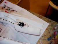
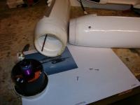
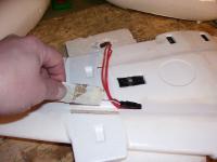
GWS 262 Mods and Removable Steerable Nose Gear No need for another build thread, just going through the motions. Not picking on any particular builds. Just meaning that it may as well be different from being a simple rewriting of the existing build manual. I'm keeping this to strengthening, hardware, finishing over iron-on Coverite, and removable gear and brake mods. Probably will get carried away with a few scale details too. The total weight of CF spars and rods used to thoroughly reinforce a fuse and wing is not much. A well engineered or reworked foamy should be robust without adding considerable weight, and it doesn't mean that performance will suffer drastically. If I can add 1/2oz, or even less, of reinforcement and pick up an undamaged plane from a doink, where another builder would be picking up their pieces after the same doink event, I'll add the 1/2 oz. As for one of my least favorite phrases that has gotten old: The "build to fly and not to crash" statements are not very relevant, considering the benefits of a very robust plane at the expense of little weight. You'll be complaining more about the expense of the CF rods than the added weight.  I often use diameters of .040" to .080, which on average are about 15" to 20" of length per gram. For example, 12 feet of reinforcing that weighs 4 grams is not too high of a penalty for the benefit. I often use diameters of .040" to .080, which on average are about 15" to 20" of length per gram. For example, 12 feet of reinforcing that weighs 4 grams is not too high of a penalty for the benefit. Pictures are worth a thousand words, so to be more clear, much of the text is under its corresponding picture. Steerable Quick install/remove Nose Gear I recently finished modifying the GWS nose gear mount, for a tubing friction fit quick-remove steerable nose gear, to use the same removable gear set that I built for my existing 262. It has the nice Robart dress kit. One more reason I got the SG kit, as I already have nice landing gear that fits both planes. They both have GWS wing landing gear mounts too. The bottom of this modified steering pivot for removable gear just clears the battery This friction tube design works well. I use telescoping sizes of K&S tubing to increase and decrease diameters of custom built pivot shafts, by simply inserting and CA gluing pieces together. It is also used to capture the fuel tubing, by plugging the end, or rounding it over. The basic concept is shown in my A10 thread, although this one is a bit different, still the same idea. I'm surprised I've got no takes on this idea, as its easy, works well, and you can install or remove the gear in about 1 second. https://www.rcgroups.com/forums/showthread.php?t=365381 GWS main gear mounts are already designed for removable gear. I've attached snap locks, made various ways, to the plastic GWS mounts for the gear wire to slip under, to avoid having to use the securing screws. Fuse Reinforcing The fuse halves have been reinforced with full length CF rods. The rods run directly under the edge of the nut holding plates for the rear wing mounts, which will keep them from tearing out. They were carfully routed to run under the plates, directly against the nut embossment in the plastic nut holding plates. More tie ins will attach to this spar structure, such as the front wing mount plate. I may just run glass or CF tape from under the front mount plate to these rods. I don't like the wing mounts ripping out of the foam on GWS planes. Not a knock on GWS, as foam is foam. Also routed a CF rod along the top center of one of the fuse halves. The structure now has 3 inner brace rods, corresponding to its outer triangular shape. The landing gear mount has been drilled and mounted with cf rods, which will index in the front ply plate. If I hit a curb now, the plane will flip onto the sidewalk before it rips the gear mount out.  Use Masking Tape to hold Fuse Halves Together Before gluing the fuse halves together, I had a bunch of long strips of masking tape ready, tacked along the edge of my building table. This works better than rubber bands for 3 reasons: 1. It doesn't dent the foam. 2. Its easier to get in place. 3. You can place it on key areas to hold the seams tight, and it stays there. Because it is wider than a rubber band, it holds the seam gap-tight over a larger area. Rudder I plan to run a CF rod along the LE of the rudder, and route it through the fuse bottom center. Since this is a high tail plane, the rudder is stressed. I've done this before on previous ME262s. Update: this has been done, with pics added. There are reinforcers at both front and rear edges. Covering This plane will be covered with Coverite Microlite, which is 0.6oz per square yard. Its not as strong as standard coverings, but extremely light, and still adds considerable strength to foam structures. It will paint, if you paint slowly. Too fast, and it will wrinkle. After the paint dries the wrinkles usually go away, and can be carefully removed under a heat lamp, but its better to just be patient and apply the paint slowly. A dust coat of primer increases adhesion. Painted Coverite does nick and chip more easily than standard coverings that are painted, but neither a perfect paint bases. I don't mind a little bit of "weathered" look anyways. One excellent advantage of Coverite is that it will stretch and shrink around a ball with ease. It applys at low temps that won't melt foam. It has become my favorite foam covering. I started realizing the real weight penalty of standard weight coverings, and got interested in the ultralights. Bill ImagesView all Images in thread
|
|
|
Last edited by scratchandbash; Jan 21, 2007 at 09:10 PM.
|
|
|
|
|
|
|
Thread OP
|
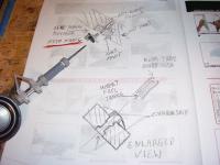
Mechanical drawing of removable nose gear pivot assembly After gluing the fuse halves together, the darn glue sept into the steering pivot area, and locked it. I kept the glue away from it, but it travels. It will now be even better. The inner aluminum tubing sleeve at the exit of the GWS plastic pivot part was only 1 alum tube thick. It will now be 2 tubes inserted together, and be stronger. Once the gear wire is installed it is strong, but this will make it stronger when flown without gear. Design option to remove the outer steering control horn piece: With this method, there would be nothing outside of the plane, without gear installed. This would involve capturing the inner tubing section, that has the rubber tubing inside it to hold the gear wire, with a plate on the battery floor. You could then simply slip the wheel strut pin loking piece in place when using gear, and then insert the gear. You would have to install in remove the pushrod this way. I actually thought about it, but I want to keep it very quick release. Main Gear and Rear Wing Hold-Down Reinforcement The main gear from another ME262 I already have (pre GWS262) will be used on this GWS262. The wire size is the same a the GWS mains, so I only needed to make nlyon locking clips to attach to the gear mounts (see pic). The gear wire snaps in place under the locking clips. I slid a DF spar under the rear wing hold donw plates, to reduce the chance of them ripping through the foam wing. It was inserted from the side of the wing saddle bottom, where a small patch of filler can be seen covering the insertion point. Bill ImagesView all Images in thread
|
|
|
Last edited by scratchandbash; Jan 03, 2007 at 01:17 PM.
|
|
|
|
|
Thread OP
|
Nose Cone Magnetic Lock
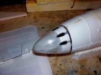
More progress. Well Mr. Bill "What Instructions?" Extraparts had to put his nose cone toghether, without reading the part about installing the spring latch, before gluing the ply plate in place. I can't complain. I decided to use Radio Shack rare earth magnets to index the nose cone in place, once the t-bolt locks are turned into position. Even when it is turned to the release position, the magnets are still close enough to hold it on the plane. I like it better than the instruction's spring latch setup. Something must have told me to pick up a few sets of these magnets the other day. I had one set before that, but I always hate using up the last set.  Still have 2 more sets now. Still have 2 more sets now.I shaped a rubber foam core for the nose with GWS rubber foam from a gyro box. It kindof like the DorkSaverTM  https://www.rcgroups.com/forums/show...&postcount=206 Realistic Turrets This isn't a structural enhancement, but the nose turrets are such a standout detail feature of the 262 that I had to make them more realistic. I cut and tapered aluminum tubing inserts for the turrets. The rears of the turret indent in the nose cone were cut out, and the tubing inserts were pushed in place and the seams CA glued. They mate the cut line in the plastic nose perfectly, with a taper previously filed in the tubing, to mate with the curved edge of the rear of the turret opening. Don't forget to file the rear of the tubing pieces 45 degrees, properly oriented to let the battery cooling airflow in. Elevator Wire tubing Inserts I glued tubing inserts into the rudder wire slots. This provides more surface area, so the wire does not tear through the foam. ImagesView all Images in thread
|
|
|
Last edited by scratchandbash; Jan 31, 2007 at 12:54 AM.
|
|
|
|
|
Thread OP
|
Adding Scale Details
I decided to add a post about adding scale details to the plane. I'm not trying to compete in the Scale Masters with the plane, but like to add/enhance the standout features of the planes I build.
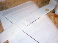
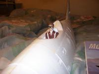
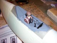
Gun Turrets The 4 gun turret opening are such a standout feature of this plane. The rears of the gun turret indents have been cut out, and short lengths of alum have been pushed in place to meet with the cut line. File a 45 degree angle on the mating end of the alum tubing insert, to meet the curve at the rear of the turret opening. I painted the inside flat black, and then primed the nose. They will need to be repainted black after painting the nose, but for now it shows the contrast in the picture below, with having real turret barrels. Pilot and Cocpit The Williams Brothers 1/12 scale is perfect for the plane. I added and shaped a light balsa torso, continuing the parachute straps across it. Other details are binoculars from an Ultimate Soldier Company soldier, mask, and earphones. Well my cocpit is finally finished. The Coverite on my plane runs into the cocpit, and covers everything but the floor. Makes it nice since you don't have to worry about paint eating foam. Well, Model Masters spray ate the foam. I wanted to avoid a brushed look, but since the floor needed a bit of filler, I brushed the pits full with filler, and went ahead and brush painted it grey. Better color anyways, just not as clean as the spray I wanted. I made a front floor out of plastic railroad detail strips, which has the footholds and heel pad detail now. More detai I wasn't planning on, but it looks good, and covers up the worst part of the floor. Other cocpit details are the "armrest" control panels, not originally molded into the cocpit, with throttle levers made from pins. The center console under the instrument panel was fabricated with foam. Moving the instrument panel back to its correct location helps scale looks. Note the rods and latches behind the cocpit, on the "rear dashboard". Not sure exactly what they are for on the real plane, but I got the detail from a plastic model photo. Elevator Lever Arms The elevator torque lever arms look nice on the real plane. On the real plane, an offset torqe crank arm is inserted in a bushing in the end of the arms, and the main torque rod runs along the hinge line. This provides the mechanical leverage to move the flaps. The rudder has one also. I made lever arms from light balsa and glued them into slots, cut into the elevator flaps. The mating cutouts are also cut into the main elevator. Do not glue them here, as they will slide up and down as the elevator pivots. The same goes for the rudder. They are a bit short, due to the elevator reinforcing rod that is in the way, but still look good. A real dashboard, mounted about 1/4" behind the front cocpit wall, looks more scale too. I made one, and put the GWS dash decal on it. Rudder Lever Arm The rudder arm is made the same way as the elevator arms. After gluing all these arms in place, fill and sand the original "simulated" indentations and grooves made by GWS. Accuraccy Not to be to tough on GWS, since I love the plane, but I noticed some innaccuracies in the "simulated" torgue arms in the elevator and rudder. In the elevator, they made "T-slot" indentations, that are to simulate the torque arms. There placement is off. I think that during the CAD design process, their placement dimensions were referenced to something other than the hinge line, and these indent features inadvertently moved, during the design process. This same thing happened to the recessed lines in the rudder, that are used to simulate the torque arm. In the picture below, the red arrow points to these misaligned lines. I've been there too, designing with ProE for 6 years. Its tought to keep up with all these details during the design process. Make real scale lever arms, and your ready for the Scale Masters.  Decals Trim as much unnecessary clear material off of the decals. The white wing "crosses" look much better if you cut out the crosses individually, without all that unnecessary clear decal material on your plane. I cut them out one at a time, and held the remaining unpeeled decal on the wing, to help locate the individual cross pieces straight and true. I also painted on simulated wing tip lights. Adding clear decal plastic over them simulates the clear lens. Wing Pitot Tube (airspeed indicator) This would also work for wing machine gun barrels. The idea is to give the gun an inner liner of flexible nylon pushrod sheathing, with a flexible Sullivan Gold Cable inside. I have found that without the gold cable, it will kink at the wing, if pushed. To increase the size, or to have a barrel with different diameters, you can slip over larger sizes of tubing. I slipped over plastic model railroad tubing, and inserted a smaller brass tube section in the end. The tube end of the full size airplane I'm modelling appeared to be brass in color. Bill ImagesView all Images in thread
|
|
|
Last edited by scratchandbash; Jan 17, 2007 at 02:54 PM.
|
|
|
|
|
Thread OP
|
Covering with Coverite
I've found this stuff to be ideal for covering foam.
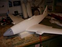
Its extremely light Applies at low temps Stretches around almost anything Can be painted, if applied slowly Even though it is much thinner than a covering such as Econokote, it still adds strength to the foam, as any iron on covering does. Provides some scratch and dent resistance when compared with bare foam, although not anywhere near as much as standard weight coverings. One thing I like about it on this plane, is that is dulls the panel lines a bit. I think they look perfect now. I've heard flyers in the past comment that the deep panel lines are not good for flight. They are still plenty visible for detail after adding Coverite, but not deep enough to cause much drag. The fuse still needs to be covered. Can only do so much of this stuff at one shot. Gotta take breaks when covering.  Fuse covered now. Panel line detail looks perfect, like the original 262s where the panel lines were filled, to leave them less noticeable. Bill |
|
|
Last edited by scratchandbash; Jan 06, 2007 at 02:02 AM.
|
|
|
|
|
Thread OP
|
More Turret and Spent Cartridge Openings Detail
This plane is so nice it just keeps asking for scale details. I previously cut out the turret openings and inserted tubing for real barrels.
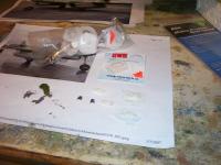
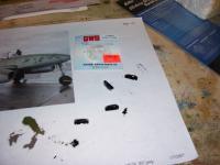
I had to add flanges for the openings now. They're made from label paper, sealed onto the nose with flat clear spray paint. Now I will have simulated turret opening flanges. Spent Cannon Cartridge Openings GWS has molded indents into the lower front area of the fuse, to simulate these 4 openings. I used the little plastic rectangular covers that are glued to the cardboard, that you get when you buy a GWS receiver crystal, to make housings for these openings. I take the plastic part, which looks like a little rectangular box, and cut the end portions off. I then CA glue these end portions together, and I have a smaller box. I've used these little recessed "boxes" for footholds on Hellcats before, and they look great. I have a collection of them, as I've always save molded plastic packaging, that looks like it may have any chance of being used as a possible detail item for a model. When finished, you have a small recessed box, with a flanged opening, that you can use for vents, footholds, or whatever else. In the first pic, it shows them under construction. In the second pic, they are prepainted. Since the pics are blurry, and they are laying in all different postions, they do not look clean. This is because only the inside portion has been pre-painted black. Once installed into recesses cut into the foam, this is the only part you will see. 1 of the 4 painted pieces is sitting upright in the pic, with the opening facing upward. That one probably gives the best view of the small finished part. Also note the 2 litte intake covers in the pic. They are made from cutoff pices of spare Guillows plastic detail parts. I have found their "bombs" to be particularly useful, since you can cut vent covers out of them, with various curvatures, depending on what part of the bomb they are cut away from. The plastic is also soft and can be shaped a bit. I then coat the inner surface that will not be seen with CA, to get it to hold its shape. Update: The inserts are now glued in place with foam safe CA. The pre-cutouts I made in the foam were intentionally undersized a bit, to create a nice tight fit, once the inserts were pressed in place. Bill ImagesView all Images in thread
|
|
|
Last edited by scratchandbash; Jan 15, 2007 at 04:30 PM.
|
|
|
|
|
Thread OP
|
Nacelle bash for removable fans
I've been getting nothing done, trying to decide for a few days, what to do with these nacelles. I had thought about reworking the front for a very scale looking EDF55 setup, but may as well keep the benefit of the larger fans.
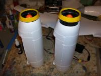
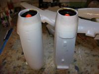
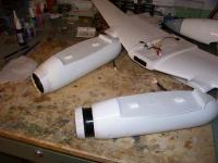
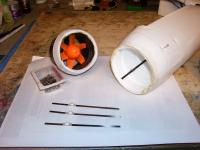
This solution is to use smaller nacelle covers from another 262 scratch build, that were unused. They are glass covered foam rings, with a balsa liner. I glued them directly to the front of the fan housings. First, the nacelle inner front diameter was enlarged by about 1/16", for the EDF64 fans to fit into. By doing this, the fans will both be removable, and add a bit of forward weight, which it seems I need with my setup. Next, the nacelles were shortened by 1/4", for the fan housing ring to fit flush with. A small round is sanded on the inner front lip of the nacelles, for the fan housing to fit into completely. The finished nacelle will be about 1/4" longer than stock, since the fan housing extension rings that were glued on are about 1/2" deep. Adding length and taper will make it look more scale. The completed fan assemblies with the extension rings were placed into the nacelles. The nacelle fronts were sanded to taper into the fan housing and its attached ring. Again, sanding off material to add taper to the front of the nacelles adds scale. Filler was then added to make a smooth blend beween the fan and ring assembly, and the nacelle. After sanding, the mating seam will be cut, to make the fans removable. I thought about just gluing them in place, but its litte effort to take advantage of the ability to remove them easily. Small reinforcement plates will be glued on to the outer nacelle surface, and screws will go through into the fan housings, to hold them in place when installed. Results of Finished Nacelles: The completed nacelles will be about 1/4" longer than stock, and have a smaller front diameter and increased front taper for a more scale look. The inlet is the same diameter as the fan. There may be a small loss, as the stock nacelle inlet has a larger round, that increases its intake diameter. The fans are also further forward than stock, adding noseweight. My build need a bit anyways, so moving the fans forward will help with the CG setting. Edit: Well the nacelles are done now. Just need to cut the joining seam, to make the fans removable. All the parts are now covered. Throw a party!  Covering's so much work. Got the seams cut, and the fasteners in place. In the past, I would put plates on the outer nacelles, for the fan securing screws to go through. It was often a hell of a time, getting them to align with the mating holes in the fan housings. This new method makes sense. I made CF spar assemblies with bushings CA glued onto them, which glue in place from the inside. The bushings provide a screw guide, and the screws will go into the fan housing mating holes with no problem now. The CF spar also runs an inch or so behind the fan, reinforcing stress concentrated areas at the rear edge of the fan housing, and the cross sectional area where the nacelles join the wing LE, where they are prone to break. Bill ImagesView all Images in thread
|
|
|
Last edited by scratchandbash; Jan 09, 2007 at 03:22 AM.
|
|
|
|
|
Thread OP
|
Harness routing into nacelles and removable servo lead
The pics pretty much explain it all, with descriptions. The idea is to make the aileron servo leads removable, and to optimize the motor wiring into the nacelles.
Bill ImagesView all Images in thread
|
|
|
Last edited by scratchandbash; Jan 09, 2007 at 12:34 PM.
|
|
|
|
|
Thread OP
|
Keep the Rud/Elv servos in place
The GWS supplied double-side tape works well for holding servos in place. I'm not concerned with them lifting out, but I am concerned that the adhesive could pull away from the foam mounting surface, over time.
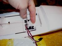
I cut a filler block, using GWS dense rubber foam, to push between the 2 servos in the fuse. Cut a bit oversize, to be compressed when installed. This stuff is used for packing in GWS receiver and gyro boxes. The pic shows it being pushed in place. Cheap insurance. Also: I bent a piece of wire and hogged out a small channel of foam, where the servo wires exit the servos and route out of the servo mounting recessed channel. I didn't like how the rubber wire strain reliefs were being stressed, when sliding the servos in place in their mounting channel. GWS: The manual obviously needs a few more details. I understand, as their was a time shortage during the release of the new model. I'd add this, and other tips to the manual. Bill |
|
|
Last edited by scratchandbash; Jan 10, 2007 at 11:32 AM.
|
|
|
|
|
Thread OP
|
Overall Painting
Finally getting to overall painting. I liked the colors/scheme of the replica made recently in Washington State, and flown in Germany. Its on the Stormbirds website. Well I matched the colors pretty well, but still haven't decided if I like them.
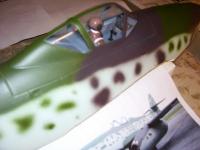
 As usual, a few mott spots a bit large, but I can live with the overall result. The full size plane is pictured below. As usual, a few mott spots a bit large, but I can live with the overall result. The full size plane is pictured below.My Better Sprayer is Having Issues: I got a decent compressor/airbrush setup as a gift. The pencil sprayer just won't work properly. The first issue was that I had to VERY CAREFULLY tweak the inner nozzle about 2 thousandths, to get it to center in the spray cap, without breaking it off, or damaging the nozzle. Seem to have fixed that perfectly, and I know from larger spray guns that the airgap must be even and clear to work properly, if at all. I plan to get a better sprayer for it. Used the Good Ol' Cheap Pasche:  I broke out the old 2 cent cheap air can Pasche airbrush, and to my surprise, the darn thing worked pretty well! The green paint is actually Model Masters medium green. I sprayed it into the airbrush's spray bottle, and filled the bottle with the spray can paint. The Model Masters spray paint was applied with the cheap airbrush setup. This worked well, with the paint unthinned and straight from the can. More on Testors Paints and Mixing: The first discovery I made was that the Model Masters can spray paint can be transferred to an airbrush bottle, and works fine. Not a real surprise, but a good option. Probably 5 times more efficient than when sprayed from the spray can. The dark brown was mixed with Model Masters bottle Panzer Grey, and plain brown enamel Testors bottle paint, with Testors airbrush thinner. This Testors cross-label mixing with their different enamel brands worked well. In the past, I have found that you don't want to try to use the wrong Testors thinner, for the wrong app.  The Testors Brush Cleaner is good for brush cleaning only, and will curd over time, if not immediately, if used as thinner. Their standard enamel thinner does not seem to be the same solution as the Airbrush Thinner, as I discovered in the past. Use the Airbrush Thinner. Their paints do not always mix with other brands either, even if they are of the same base, being enamel or lacquer. Also, be careful as some of the sprays are enamel, and some are lacquer, in the Model Masters label. I think all of the standard Testors labelled sprays are enamel. The Testors Brush Cleaner is good for brush cleaning only, and will curd over time, if not immediately, if used as thinner. Their standard enamel thinner does not seem to be the same solution as the Airbrush Thinner, as I discovered in the past. Use the Airbrush Thinner. Their paints do not always mix with other brands either, even if they are of the same base, being enamel or lacquer. Also, be careful as some of the sprays are enamel, and some are lacquer, in the Model Masters label. I think all of the standard Testors labelled sprays are enamel. As always, the wing should go easier today, now that I've already have some time in with the sprayer and the paints. Bill ImagesView all Images in thread
|
|
|
Last edited by scratchandbash; Jan 17, 2007 at 03:50 PM.
|
|
|
|
|
Thread OP
|
Official Rollout
I still have a few minor details, since its easy to just keep going with them, but its pretty much finished now. I'll have to stare at this one for a while. GWS made a pretty plane for us. Gotta let 'em sit until you get over the jitters.
Bill ImagesView all Images in thread
|
|
|
Last edited by scratchandbash; Jan 18, 2007 at 10:23 AM.
|
|
|
|
|
Thread OP
|
Thanks. I hope happy flying. In reality, what this has done is taken my sentimentality away from my other 40" 262 build. I may take it out first, since I'm now less worried about it now. I like this GWS one. I shouldn't say it, but I'm known for maiden delays. I've had planes that got maidened 2 years later.
 Bill |
|
|
|
|
|
|
|
Thread OP
|
Thank you much Gunracer. I really wanted to do a historical scheme, but I kept looking at that replica and I liked the colors and scheme so much. It was basically a 50/50 coin toss, on deciding to use the scheme. I'm glad I did.
Bill |
|
|
|
«
Previous Thread
|
Next Thread
»
| Thread Tools | |
| Similar Threads | |||||
| Category | Thread | Thread Starter | Forum | Replies | Last Post |
| Sold | 1/4 scale steerable nose gear | SRush99 | Aircraft - General - Miscellaneous (FS/W) | 0 | Jun 18, 2006 05:41 PM |
| Help! | A-10 Steerable Nose Gear | Allan Aguilar | Parkflyers | 8 | Mar 09, 2006 06:54 AM |
| Steerable Nose Gear | ariesmars | Electric Plane Talk | 8 | Dec 19, 2005 03:57 PM | |
| Dave Blum Cessna 182 Steerable Nose Gear | bnflyn | Scale Kit/Scratch Built | 5 | May 20, 2005 11:29 AM | |
| Has anybody made an X250 with steerable nose gear? | Joe Elston | Electric Plane Talk | 13 | Jun 24, 2001 05:34 AM | |

