|
|
|
|
|
Question
Head & Rocker Removal? - New (never run) Saito .62
Hi all. I need some guidance on something with a new Saito four stroke I'm using on a kit build I am doing. Thanks in advance for any insights you can provide on something I've never done before.
First a brief explanation. I am in the late stages of a Sig Kadet Sr. kit build. I am using a custom made fiberglass cowl which I have started the fitment on. I have a new Saito FA 62B that I will be using in this build. I have the engine mount located on the firewall so that the Saito's cylinder head is rotated 90 degrees to the right with the cylinder head protruding out the right side of the cowl. This location also has the exhaust protruding out the bottom and the carb adjustment pin up on the top of the cowl. (p.s. unrelated but engine mount was also located per Sig instructions to achieve proper right thrust, etc.). So as I sit here and consider all the many tips and tricks I've read about for cowl fitment and cutting, it seems the whole process would be so much easier if I could first just install the engine on its mount without the cylinder head in the way. I could then slide on and do all the alignment and cutting of the cowl to accommodate the prop shaft - getting it centered in the prop shaft hole and ensuring the front of cowl was set back from, and aligned perfectly with, the TruTurn spinner backplate I am using. Once all that was all perfect, I could mark and install the brackets and screws that hold the cowl to the firewall/fuselage. With all of that done, I would know that the cowl was now installed in the correct location. I could then reinstall the cylinder head and exhaust onto the engine and use one of the many alignment techniques I have read about for determining how to best mark and cut their locations on the cowl. So this brings me to my question which is, can I remove the head and rocker arms, rocker covers, etc, on this brand new, never run Saito .62 without special tools? Without having to purchase and install new gaskets or seals? In other words, would this be a simple disassemble/reassemble task or would I need special tools such as a press or special gauges, new gaskets or seals, etc? I ask because I don't have any experience tearing down an RC engine and I really do not want to compromise a brand new Saito in any way. Nor do I want to create another big project for myself that in the end won't save me any time. As always, thanks for all your help and advice! -Matt |
|
|
|
|
|
|
|
|
|
|
If you don't have any experience rebuilding a RC engine I really do not recommend it. Especially if it is a four stroke engine.
For many two stroke engines we do take off the cylinder head to make it easier to fit the cowl and then re-install the cylinder head after the cowl is in place. However I don't take off the cylinder head while trying to trim the cowl to fit the engine. I don't want any rubbish falling into the engine. One suggestion I have is to make a dummy engine and use that as a template to cut the cowl. Build the engine with what ever materials you are comfortable with. Just measure the dimensions of the engine and duplicate it. For me personally I can do some drawing on the computer and I either draw the engine or if I am lucky I can find a drawing file of an engine by searching online. I also have a 3D printer and I print out a 3D fake engine and use that as a template. You can mock up the bottom half of an engine but using a large diameter wooden dowel. OS used to sell flat metal templates that you can mount on the engine mount and set the cowl distance from the firewall from the template. Another alternative and much less costly is to find a used and abused Saito FA 62 engine for parts. Strip the top half and use only the crank case and crankshaft. The one pictured is my 3D printed template for an OS 50 FSR. |
|
|
Last edited by SeismicCWave; Oct 21, 2021 at 12:35 AM.
Reason: Another idea.
|
|
|
|
|
|
The cylinder base bolts on a Saito need to be really tight, and they would be nearly impossible to tighten inside a cowl. As you can see they are way down from the rocker covers.
|
|
|
|
|
|
|
|
|
SeismicCWave,
Thank you. Exactly the kind of advice I was looking for. I actually did create a "mock-up" of the engine using a block of wood that installs directly on the engine mount with a dowel that represents the prop shaft. The dowel is also marked with the expected location of the spinner backing plate. The only issue is I don't completely trust the location and dimensions are identical. I guess that is where I'll focus - ensuring the mock-up prop shaft (made of dowel) truly is located and dimensioned exactly like the engine itself. Thanks again. -Matt ITOBOR, Thank you for the reply. I don't forsee the need to install the cylinder head with the cowl on but thank you for the insight. -Matt |
|
|
|
|
|
|
|
|
Matt. If you have a mock up engine it only needs to be close. Use it to mount the cowl, but only put in a couple of small screws. Mount the engine and cut the cowl really tight to the engine and reinstall the cowl. If you need to adjust the cowl slightly it is no problem as you will have to enlarge the engine opening in the cowl anyway. If you can get the cowl within 1/8" or so you can adjust it after the engine is mounted. Then install the permanent mounting hardware.
Scott |
|
|
|
|
|
||
|
|
Quote:
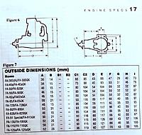
I did a quick Google but Horizon/Tower website did not have a manual for the FA62 readily available. If you want you can take a picture of the manual of the engine with the dimensions of the engine. I can probably print a mock up for you. |
|
|
|
||
|
|
|
|
|
I hope this is readable.
|
|
|
|
|
|
|
|
|
Scott,
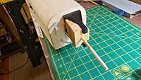
Thanks. What you are saying makes sense and helps. My pursuit of perfection in process sometimes gets in the way. I need to be reminded at times there may be a more simple/straightforward approach. Thanks! ITOBOR, Thanks so much for going to all the trouble of trying to share that info! SeismicCWave, I was able to see that the centerline of the prop shaft aligned with the bottom of the engine mounting lug. Below I am sharing a picture of my wood mock up I had created where you can see this. Note that the wood block part of the mockup fits tightly between and into the engine mount. The pencil line you can see around the dowel represents where I believe the back of the spinner backing plate will be. So I understand the concept of how to creating an engine mock up I can use to get the cowl lined up correctly with the prop shaft and mounting plate. Where I struggle and why I don't entirely trust my mockup is that I do not own the right tools (or have the right skills? or both? :-) )to create one that I can trust. For example, and I realize this is way too much information, but I don't own a drill press. So as an embarrassingly crude workaround, I marked the location of the dowel where it should be located on both the front and rear of the wooden block. I put the block in a vise and using a hand drill, I then drilled in half way from from the front of the wood block and then turned it around and drilled in half way from year until the holes met. Then pushed the dowel through. Very crude I know but I couldn't think of a better way. This starts to get why I don't have complete faith in my mockup. See photos and additional info below. Sorry for another overly long-winded post on my part! :-) ImagesView all Images in thread
|
|
|
Last edited by MattKennedy; Oct 22, 2021 at 08:47 AM.
|
|
|
|
|
|
Matt, here is a picture of the short lived 62-A.
|
|
|
|
|
|
||
|
|
Quote:
|
|
|
|
||
|
|
|
|
|
Thank you all for your help. I just re-mounted my engine and rigged up something on the workbench in front of the plane to mark and hold the exact location of the tip of the engine shaft. I then swapped out the engine for the mock up and the tip of the mockup shaft matched within a 16th or so. So given your advice, I am going to proceed with marking and cutting the hole for the cylinder head in the cowl but on the tight side as Scott suggests. This should leave me some room for additional adjustment and trimming if I am off by a little bit.
Thank you all again. Don't mean to make this bigger than it is. Just would hate to have to order and wait for a new custom fiberglass cowl. Thanks a million! -Matt |
|
|
|
|
|
||
|
|
Quote:
|
|
|
|
||
|
|
|
|
|
Cool and thank you for the generous offer. After re-measuring the crude wood mockup I had made, it seems to be pretty close. I'm going to proceed as I'd outlined above. Once again thanks! -Matt
|
|
|
|
|
|
|
|
|
|
|
|
|
«
Previous Thread
|
Next Thread
»
| Thread Tools | |
| Similar Threads | |||||
| Category | Thread | Thread Starter | Forum | Replies | Last Post |
| Help! | BME 62 Petrol - not running. | Pattern_flyer | Engines | 2 | Apr 02, 2016 09:23 AM |
| Discussion | Saito 100, Never Ran, head cracked at muffler :( | eobie | Engines | 13 | Jan 31, 2013 01:48 PM |
| Discussion | Running a Saito 62 FS without a muffler? | jhamm | Fuel Plane Talk | 1 | Jul 28, 2007 07:04 PM |


