|
|
|||
|
Thread OP
|
Video
How to make a Halbach rotor (2min.)
Other Halbach motor videos by Mohammad Imani Nejad
www.youtube.com/user/imanmamed1/videos
Halbach Hallbach Halback Hallback |
||
|
|
|||
|
|
|
|
|
|
|
Certainly an effective way to do it, but seems like a waste of magnet weight since they have to be a few mm longer than the stator in order to reach under those lips. I feel like there's some better solution, like making notches in the ends of the magnets or something to provide a gripping point that doesn't require any structure encroaching toward the stator. It would puncture the magnet's corrosion-proofing, but that's probably ok assuming they're glued in with epoxy which would re-seal it.
I'd also like to devise a method of making the rotor out of carbon fiber. Lighter weight, and easier to wrap fiber around a mandrel than to machine a large diameter/short length/thin walled tube. And since the magnets try to pull toward the center, you could assemble them around the mandrel and wrap the carbon directly onto them, eliminating the separate magnet installation step. Just need to figure how to do the end cap/shaft mounting part. And it would certainly need some balancing after it's done, which may be a problem since there's no space between magnets to add mass lumps like with non-halbach motors. EDIT: Upon further study of the diagrams on wikipedia, I don't think assembling the magnets around a mandrel would work since it's a repulsive force we're dealing with. After attempting to design one, I think the reason they're not more common is because available magnet sizes and stator sizes are so limited. I don't know how the guy in that video managed to find a combo that results in full coverage like that. Probably will need a little shim inbetween each magnet, or to grind a little material off of half of them. That second option may be a good thing though, since you could grind the radial-facing magnets to a trapezoidal shape to get some mechanical locking that way. Of course that will remove the corrosion-proofing again, but on second thought it may not be anything to worry about since there's already exposed iron on the ends of the stator arms. |
|
|
Last edited by dekutree64; Aug 24, 2021 at 11:55 AM.
|
|
|
||
|
|
Quote:
Although one thought regarding locking them in place is that you could mill small grooves in the sides of the magnets and use wire to pin them in place like a keyway. I've attached a closeup image of 8318 with 1/8" magnets and 1mm pins. You do lose a tiny bit of magnet mass, but given that the starting amount is decided based on what's available rather than any calculated ideal magnet size, it could just as easily be an improvement. But I don't have any immediate use for an 8318 motor. I'd rather make a rotor for a 5010 motor that have, which would also keep the experiment nice and cheap. Its stator is 40.5x6mm, so about 9.2mm to be divided between each radial and side-facing magnet pair. 6x5x2mm for the radial magnets and 6x4x2mm magnetized through the width (or two 6x2x2mm) for the side-facing would be good, but so far no luck finding any of those sizes. |
|
|
|
||

|
|
|
|
|
I think having the magnet longer than the stator need not be a total waste and need not be much material and the magnets are so hard just a millimeter on either side and could be held in like he does it in the video above. Being able to get them held in position..his way above seems very good.
I was going to make a bunch of hallbach but after seeing how little effect it had with the very thin sideways magnets I was using and how thick the back iron is it seems not worth it. (Then again I haven�t been able to build it and pretty sure I have the sideways magnets in wrong and was too easy). I also got the sideways magnets in two parts as they were too long to get made as one, so can�t use the method in the video with the lips regardless. I�d planned on using a dowel in the rotor and the magnets sliding tightly between the rotor n dowel. |
|
|
|
|
|
|
|
|
Yeah, 1mm extra magnet length on each end should be ok for anything but really flat pancake motors. It's in close enough proximity to the stator that it may contribute some useful field, and can't be too much dead weight regardless. Larger neo magnets have heavily rounded edges which would be a problem, but fortunately halbach requires narrow magnets so the edge rounding shouldn't reduce the grippable area by much.
The motor in that video appears to have about 40% of the length devoted to the retainer lips. Not sure how much is magnet length versus aluminum to reach around the magnets, but either way that's quite a lot of dead weight. I came up with a solution for my 5010 motor, which is to change to 12N10P configuration and use 1/4 x 1/4 x 1/8" radial-facing magnets and two 1/4 x 1/8 x 1/8" for side-facing. That leaves less than 0.1mm gaps, and conveniently has the same winding configuration as 12N14P. Not enough extra magnet length to use retaining lips, but at this size epoxy alone may be enough. Especially since the gaps between magnets can be filled, and the sides can be roughed up to provide more grip if necessary. I don't quite understand your dowel idea. Is it something that only assists with the assembly and then is removed after the epoxy sets up? I'll order the magnets and 3D print some assembly jigs to get a feel for what will work before I bother making anything high precision. |
|
|
|
|
|
|
|
|
He talks about four movies he made showing how he builds the hallbach but I don’t see that in the short videos.
It’s hard to see in the video but the clip must fit under the stator. it must be like .4mm thick. i guess it cant be steel. i guess aluminum that thin is good enough. and still using all the magnet possible just limited to an airgap that need not be that big really looking at his video. .2mm thick clip? id like to see the clip in detail. if making a hallbach id think youd want enough poles that the magnets were square, and then a square sideways magnet capturing as much of the field as possible. |
|
|
Last edited by Hummina; Aug 26, 2021 at 11:30 PM.
|
|
|
|
|
|
Yeah, I actually decided to hold off buying the 1/4" length magnets yesterday because it occurred to me there's also the option of buying a 4112 motor and rewinding it for 24N20P with 1/2 x 1/8 x 1/8" magnets. I've never wound a motor before, so that would be another good learning experience (though not one I'm looking forward to since all the information on it seems to be scattered around and buried in long threads).
According to the bavaria-direct calculator, there appears to be another interesting option that uses the same winding scheme as 12N14P, but with 38 rotor poles (76 magnets for halbach!). For the 5010 motor I originally wanted to use (which has 4006 stator with 12 slots), 1/4 x 1/16 x 1/16" magnets work out pretty well. I wonder if halbach needs more magnet mass to make up for the missing back iron mass, or equal magnet mass and the back iron mass is simply eliminated? Depending on the answer, that arrangement will either be a good weight reduction or a bad strength reduction 
|
|
|
|
|
|
|
|
|
This should be the number one thread! A few questions:
I'm interested in a halbach array like this because I want a motor with a high torque and a low kv as possible with no transmission. Is this a step in the right direction? Can a woven carbon fiber tube be used as the backing for this type of halbach array? I suppose aluminum is much easier and probably good enough. If a guy was industrious, could he take rectangular (cheap) magnets, say 1 x .25 x .25, and grind them into the proper "pie" section shape (angles, inner and outer radius determined by motor design), then recoat them with something to protect them again? Time consuming and possibly dangerous particles during grinding, so probably not worth minimal gains? If you were to use regular rectangular magnets, like the example, could you fill the internal air gaps with a metal filled epoxy, not only to fill the air gap, but to also hold the magnets in place (resist radial inward magnetic force) by making the whole magnet array like a solid ring (like a brick bridge arch). Does this graphical representation correctly depict a halbach array? Say red is north and green is south. |
|
|
|

|
|
|||||||
|
Thread OP
|
Quote:
To get some idea. Quote:
Quote:
Eddy current losses in aluminium? Quote:
Moisture in the air can turn magnets into mush. Quote:
Quote:
Magnetism oritentation has to rotate 90� with every step/magnetpole advance. From en.wikipedia.org/wiki/Halbach_array 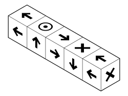 Cross is current or magnetism moving away from viewer, circled dot is magnetism or current towards viewer Vriendelijke groeten  Ron Ron• Without a watt-meter you're in the dark ... until something starts to glow • • E-flight calculators • watt-meters • diy motor tips&tricks • Cumulus MFC • |
||||||
|
|
Last edited by Ron van Sommeren; Mar 03, 2022 at 08:51 AM.
|
||||||
|
|
|
|
|
Hi Gordon,
You graphical is right. with rectangular magnets. If you like , you can also build a Hallbach array with cylindrical magnets like in the paper here, https://arxiv.org/pdf/2008.07339.pdf , on page 5 . With cylindrical magnets you can adjust the magnet like you want , possible a little asymetric design for higher torque in one preferred rotation direction. But need a flux mesuring hall sonde to get all the same flux. Happy Amps Christian |
|
|
|
|
|
|
|
|
And here are the stepped magnets, probably expensive since they may be custom made.
https://www.google.com/url?sa=i&url=...AAAAAdAAAAABAc |
|
|
|

|
|
|
|
Thread OP
|
How would you use them? In combination with slots, keyed? Or tiled ...?
Vriendelijke groeten Ron
|
|
|
|
|
|
|
|
|
You could hold the magnets in place similar to the method in the video, but without the rotor going into the air gap and without having too long of a magnet.
To do a halbach array you need 4 different magnets though, with the magnet field going through each of the 4 longer faces. |
|
|
|
«
Previous Thread
|
Next Thread
»
| Thread Tools | |


| Similar Threads | |||||
| Category | Thread | Thread Starter | Forum | Replies | Last Post |
| Discussion | How to convert to halbach? | Hummina | Electric Motor Design and Construction | 11 | Dec 22, 2016 01:19 PM |
| Question | how to make a dual rotor heli | bradleyK | Multirotor Drone Talk | 12 | Jun 16, 2010 10:52 PM |
| Discussion | Any one know how to make a rotor hub for a honey bee fp? | slo123 | Micro Helis | 12 | Apr 02, 2007 01:13 AM |
| Mini-HowTo | How to make a quality rotor in an Hour and 10 simple steps | gguy | Auto Gyros | 0 | Oct 16, 2006 10:18 PM |