|
|
|||||||||||||||||||||||||||||||
|
Thread OP
|
Great Planes Siren Hotliner ARF ReviewIntroduction
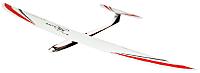
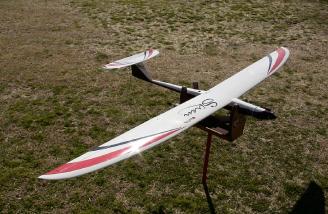
The Great Planes Siren is marketed as an entry-level hotliner. There has been much debate on these forums about whether this model can fill those shoes. I have owned and flown many hotliner designs, and jumped at the chance to review this one! Its large wing appealed to me, as it would make for stress-free launches and landings. Additionally, if you choose to thermal the model, a lighter wingloading will help, and its large wing would make it easy to see!
Kit Contents
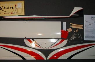
The model was well packaged, with all parts in plastic bags, and separated by cardboard inserts to prevent them from damage. It was shipped double-boxed, with a sturdy brown box surrounding the printed display box, and the model arrived with no damage.
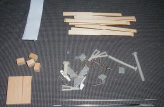
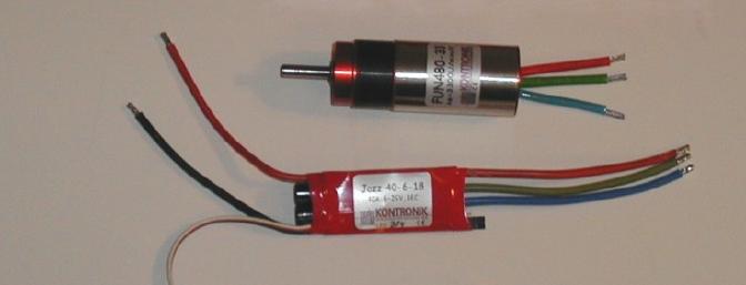
A nice touch is that all required hardware is provided. The plastic clevis and control horn hardware is not typical for a hotliner style model, but is adequate for this particular model as described later. For this review, Hobbico was kind enough to provide the Kontronik Brushless Set 480, which includes the Kontronik 480-33 brushless motor with the integrated KPG25 4.2:1 gearbox, as well as the Jazz 40-6-18 ESC. They also provided an 8-cell 2000mAh NiMH battery. Note that the recommended brushless power system calls for 10 cells, but this will be discussed later in more detail.
The power system required installation of the Kontronik bullet connectors between the motor and ESC. It is usually sufficient to directly solder the wires between the ESC and motor, but these connectors allow the motor or ESC to be switched out at a later time. As it happens, due to the location of the battery tray, the installation of these parts required the use of the connectors, so the modeler should plan on installing them. I also planned to experiment with different power systems at a later time, using the connectors would simplify removal of the ESC or motor.
Assembly
The instruction manual provided with the kit is first rate! Not only does it provide detailed, step by step photographs and instructions for assembling the model components, but it also provides information on power system choices. This is important in a model such as this - as an "entry level" hotliner, manufactured and distributed by a leading name in the radio control model industry, it is sure to attract many non-electric modelers. One barrier preventing many of these modelers from trying an electric model is the power system selection. To a newcomer, the choices available can, and often do, overwhelm them. There are many trainer and parkflyer style electric models available, which often provide good power systems as a part of the kit, but these do not always appeal to the experienced pilot. Therefore, providing a good "primer" on power system selection in the instruction manual should be applauded. The instruction manual is available online, so the reader could review this models assembly sequence prior to purchase. Note that there is a recommended power range of 200-500W for this model.
Wing
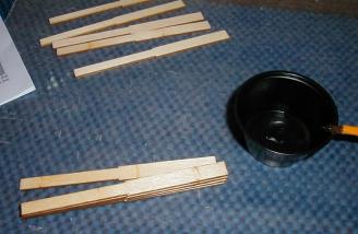
Assembly of the model begins with the wing. The wing is of built-up wooden construction, fully sheeted, then covered, and requires assembly of three panels. The ailerons are also wood, and pre-hinged with clear tape on both the upper and lower surfaces. The assembly of the wing only takes two pages to describe, and takes little time to complete. There is little value in duplicating the steps as this information is already provided in the instruction manual, but I have included pictures of some of the more unusual steps.
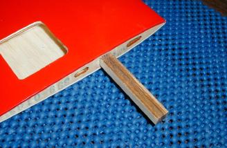
The wing joiners are certainly unusual or, at least, unexpected, for a high performance model. They are more than adequate, however, as the center panel is quite large, and the loads at the wing panel joints are much lower than at the root. Five pieces of laser-cut plywood are epoxied together, and then glued into the wing panels, which are also joined at their roots with epoxy. I'll add, however, that you need to mix up small batches of slow curing epoxy for the task of joining the wing panels. If you use too much, or a fast cure product, it will harden in the mixing cup before you have time to assemble the panels. You must assemble one panel to the root at a time, taking your time to ensure a good, tight fit, and checking the alignment before taping the panels together. Then mix up a new batch for the other side. Assembled correctly, the one piece wing will be sturdy, and, I have been assured, within the stated power system limitation can withstand any abuse you can throw at it!
Once the wing panels are joined, you install the aileron servos and associated linkages. Nothing too unusual here, except perhaps for the plastic control horns - one might usually expect to see sturdier hardware on a hotliner model, but again, I was assured that the provided hardware is adequate for the model when flown within the recommended 500W power limitation. I used the provided hardware, which made short work of the control linkage installation. One time saving tip here - in order to thread a pushrod into a plastic clevis, I put a small right-angled bend into the end of the rod, and insert it into my cordless drill. I thin hold the clevis securely, and run the drill to thread the pushrod as required. The end of the rod will need to be trimmed down anyway, as the provided rods are much longer than needed.
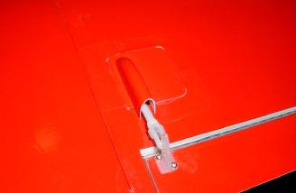
After installing 24" long aileron extensions through the wing using the provided string, the servo covers need to be trimmed and installed. The instructions direct you to use the provided screws to hold these in place, but I cut my covers down so that the fit neatly into the opening, and used tape to mount them flush with the surface. The wing was now complete! Total time spent on this, not including the time it took for the glue to cure, was less than two hours. Aileron surface throws were set to the recommended 9mm on high rates, and 5mm on low rates. I had taken care to install the servos such that there was ample throw in the 'up' aileron position to allow for spoileron operation (raising both ailerons to act as "spoilers"). Although I could not be sure if it would be needed, it would be inconvenient to reconfigure the servo arms and linkage to allow this at a later time.
A note of caution - you should ensure that your chosen servos and servo arms, with the linkages installed, will fit beneath the provided covers before you secure the servos in place. Double-sided tape is useful when testing the fit and movement of these servos and linkages. Once everything is installed, you might want to trim down the screws that hold the control horns in place. I used a Dremel cutoff wheel - but was careful not to overheat the screws and melt the plastic retainer.
Fuselage
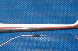
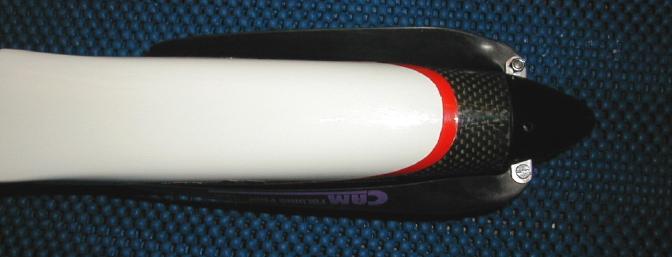
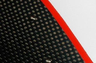
The fuselage is a work of art - the exposed carbon cloth looks very "sporty", and the contrasting white gelcoat, and red trim stripe add to the effect! There is a cutout already provided in the tail for the elevator servo. I must say, I was most impressed with this servo placement - many glider manufacturers should take note, that short control linkages with servos mounted in the tail are much preferred to running long flexible pushrods from under the wing. This provides more flexibility in battery placement, which usually helps to get the CG correct.
Tail
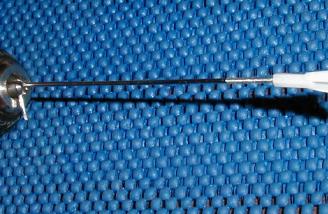
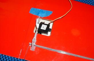
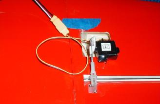
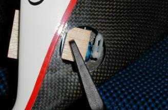
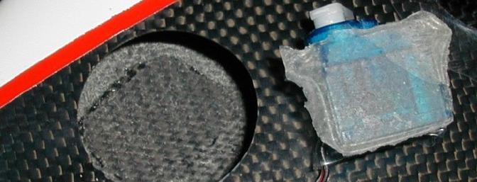
The horizontal stab has the elevator attached - pre-hinged with tape just as with the ailerons. The provided 2" nylon bolts need to be cut down to about 3/4", and once installed they hold the stab securely. The linkage for the elevator servo is made up just as with the ailerons - a threaded rod, plastic clevis, and a z-bend - but the elevator control uses the z-bed at elevator surface. The control horn needs to be drilled out to allow the z-bend to pass through it. After cleaning and sanding the inside of the fin to allow for secure attachment, the servo is then wrapped in heatshrink, and with the tail in place to ensure everything is lined up correctly, the servo is epoxied in place. I was not comfortable with this mounting, however, as I have had difficult bonding to in inside of glass, kevlar and carbon fuselages in the past. You will find later in this review that my concerns were justified, and I use a different mounting method to remedy the problem.
The recommended elevator surface throw is 12mm on high rate, 8mm on low rate, which was easily accomplished with this linkage arrangement. The instructions recommend a 24" servo extension, but as can be seen, a 12" extension is more than sufficient.
Power system
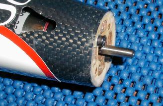
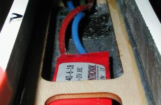
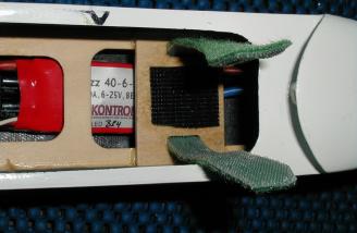
As mentioned, the provided power system required connectors be soldered to the wires between the ESC and motor. I added a Deans connector to the battery side of the ESC. The ESC would fit nicely underneath the battery tray, but the only way to connect the motor and ESC wires was to route them underneath the tray. I first slid the motor into the nose, then back towards the tray, so that its wires came back underneath the tray. I then used a couple of pairs of long-nose pliers to reach forward and connect the wires. It was simple to accomplish, and I would strongly recommend the modeler do this no matter which power system they install. The fuselage is narrow, and once the battery is installed on top of the tray, there is no additional room for wires or the ESC.
The motor was then secured with two metric screws and small washers. Washers are important here, as the ply motor mount is easily compressed as the screws are tightened. Although I was provided with the recommended APC 13x7 blades, the required spinner/yoke combination was not available, so I chose a 38mm HM Litespinner with a 40mm yoke (I keep plenty of parts on hand!)
The spinner has a carbon fiber look to it, so it matches the fuselage well. The built-in yoke uses small bolts and lock nuts to secure the blades, and makes quick and easy work of switching out different blades for fligt testing. I chose a set of Aeronaut 13x11 blades to start with - more on prop and battery selection later. These were installed, and within just 45 minutes (again, not counting the time it took for the epoxy to cure), the fuselage was complete.
Completion
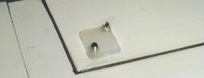
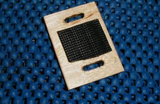
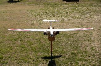
I chose a Hitec Electron 6-channel receiver for this model. With the antenna wire run beneath the rear edge of the pre-installed battery tray, the receiver drops nicely into the rear opening of the tray, and I secured it there with Velcro. I planned to plug the ample aileron extension wires directly into the receiver, so using Velcro here made for easier assembly at the field. The provided battery slides along the top of this tray, and with the battery pushed forward as far as it can go - right up against the motor - the model balanced at the recommended CG point (55mm behind the leading edge). This was extremely fortunate, as I did not want to have to add any weight to balance the model. The position of the battery meant there was no easy way to secure it without some additional modification. The instructions suggest using a foam block, but as I planned to try different batteries, I chose to install a small Velcro strip, and a Velcro strap to hold the battery against the strip. This is my usual method of securing a battery in a model - the strap must be securely mounted to the fuselage or, as in this case, the battery tray. In this model, a small tray was required for the Velcro strip and to hold the strap, as there was insufficient material available to secure the strap to.
With this tray installed, I could now quickly install and secure in place the various batteries I intended to use.
The completed weight of the airframe was 32.1oz, the wing weighing in at 13.8oz, and the fuselage 18.3oz. With the provided 8-cell NiMH battery, it came to 45.4oz.
Radio programming
As discussed earlier, I had configured the aileron servos and linkages such that spoilerons would be available if needed. Therefore, I when programming my Evo for this model, I included spoilerons, so they would be available if needed. The Evo makes this a very simple task, but it is important to point out that you must ensure your radio supports not only spoilerons but also reverse differential. As the ailerons rise towards their physical endpoint limits, reverse differential reduces the amount of "up" aileron travel, and increases the amount of "down" aileron travel on the opposite aileron. This ensures not only that no damage is done to the servos, but also that you have positive aileron control in the "spoilers-deployed" mode. I assigned spoilers to the throttle stick, as power would be controlled by a push-button on the side of the transmitter. There is no need for partial throttle in a hotliner-style model. Finally, elevator and aileron throws were calibrated, with full-rates set a little higher than the suggested maximums, and low rates set at about 50% of that.
Power system selection
Battery
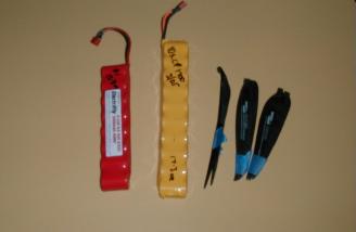
I selected a few alternate battery packs - an 8-cell pack of 1950FAUP NiMH's, a 10-cell pack of GP1100 NiMH's, and the day of the first flight tests, I made up a 10 cell pack of CP1700's - this pack would be similar in size and weight to the suggested 10-cell pack, and I felt it was important to assess the handling of the model with the additional weight on board. The selected packs weighed 11.4oz, 7.4oz and 17.3oz respectively - the provided battery weighed in at 12.8oz. This would allow for flight tests at a read-to-fly weight between 39 and 49oz. The 10-cell CP1700 pack, when mounted as far forward as possible, moved the CG back from the recommended 55mm point to about 66mm. I would test-fly the model and adjust the CG rearward with the provided battery before attempting to fly the alternate packs. The 10-cell pack would not fit through the fuselage opening. The tray is high enough that you would literally have to bend the battery to get it to fit! It did not take much work to remedy this situation, however - I simply used a rotary tool with a small diameter sanding attachment to remove approximately 3/16" from the front of this opening. NOTE: The fuselage is constructed from carbon, and the dust generated is extremely dangerous to the lungs and eyes. Check to see that you can install your battery without modifications, and if necessary, perform this task taking appropriate precautions - eye protection and a dust mask, and preferably an air source to direct the dust away from your work area. I often cut or sand carbon fiber outside, rather than in my enclosed workspace.
A prop-selection primer
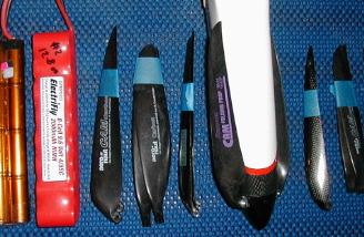
With a small selection of batteries, I rummaged through my prop collection and came up with a few that could be used during flight tests. Although calculations (using any of the number of software packages or online systems) help you get "in the ballpark", there is no substitute for flight testing. Therefore, I selected props that would load the motor sufficiently to get current draw in the 40-60A range, using the different batteries. I did not spend hours laboring over the numbers - with a good selection of props on hand, once can quickly determine what works well during test flights. Changing folding-prop blades can be accomplished quickly, but do take care not to drop the bolts or nuts in the grass (yes, don't ask..) With some rough numbers for the power requirements with various sized props, I selected 12x8, 12.5x10, 12.5x13, 13x11, 14x10 and 14.5x14 blades to take along for the first flights.
The recommended brushless power system calls for 10 cells and a 13x7 propeller. I ran some numbers and found that the 13x11 prop with the 8 cell pack provided would provide less power than the suggested setup. As the assembly of this model was relatively simple, however, I wanted to include information on power system selection and tuning. Therefore, I would accept a slightly lower power system - perhaps a closer representative of a cheaper, brushed motor setup - for my initial test flight. The reason for choosing a high-pitch prop is that most models designed to fly at relatively high speed benefit from this high pitch:diameter ratio. I have flown many hotliner, pylon and F5B models, and although you can get a "more impressive" (crowd-pleasing) vertical climb out of a lower-pitch (and higher thrust) prop, measuring rate of climb shows that you are better off with a high-pitch prop and letting the model fly at a much higher speed. Although you may achieve the same altitude with either setup, the real advantage comes at the end of the climb, where a lower-pitch setup will result in a lower airspeed once you power-off. Hotliners and F5B models all need to maintain a high speed (except when thermalling or landing, of course!) and one of the most important skills in flying these models is learning to maintain energy. Achieving a high speed at the end of a vertical climb contributes a great deal to this goal. The other skills involve flying in a smooth and gentle, yet aggressive fashion, and are beyond the scope of this review (and, unfortunately, somewhat beyond this pilot's ability!) A simple analogy might be to compare prop selection to gear selection in an automobile. While a low gear may allow you to accelerate quickly, you can reach the RPM limit of your vehicle quickly, and that gear would be inappropriate for most trips. A higher gear may make it more difficult to get moving, but once you are, you will be able to travel great distances with relative efficiency. The same principle applies to a model that is designed for speed, such as a hotliner. Although you may have an easy launch and an impressive climb angle with a low-pitch prop, you will reach the maximum speed very quickly, and the model will never reach the speed at which it was designed fly (until you put it into a dive, of course). With a high-pitch prop, the launch may not be as easy, but the model will quickly accelerate well past stall speed, and then will fly under power at a speed much closer to that it was designed for. You can now maintain a much higher speed, power on and power off, when desired. As it happens, a lightly loaded model like the Siren will glide easily, and safely, even from a modest throw, so you do not have to be concerned with the launch. This is an over-simplified analysis of prop selection, but I hope some readers will find it useful to help understand why high-pitch props are more appropriate to high speed models. Also, note that a more traditional, low-pitch prop may be appropriate in very low power setups, in order to have sufficient thrust to allow the model to climb at anywhere near an acceptable rate.
Flying
Test flights
The first test glide immediately justified the configuration of spoilerons. The model floated so well, had I not had them enabled, I would have flown straight into the fence at the other end of the field's 400' landing area! The model flew straight and, with just a couple of small adjustments to the elevator, level from that first test glide. I could immediately see that this model would be easy to launch - and thanks again to spoilerons, easy to land. I strongly encourage the reader to configure spoilerons on their model. Otherwise, you will have difficulty landing in all but the largest fields - and attempting to go around from a missed approach is inviting disaster. Unfortunately, the first trip to the flying field ended after the second test glide. Upon retrieving the model, I found that the elevator servo had popped loose. This servo had been securely mounted to the side of the fin, after the surface had been sanded and cleaned as per instructions. The epoxy had pulled cleanly off the surface, however - and what was more amazing, is that it was still securely attached to the smooth heatshrink covering on the servo.
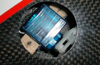
I remedied this situation by removing the heatshrink, and using CA to secure two small wooden blocks to the side of the servo. I then wrapped that assembly in heatshrink, used Goop to secure it to the inside surface, and drilled holes through the blocks and out through the fin. I then used small servo-retaining screws to secure this in place.
Test flights - Second attempt
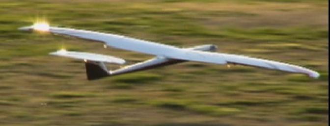
With that problem resolved, the next trip to the field resulted in a problem-free flying session. I installed the provided 8-cell pack, and with the 13x11 blades installed, I did a quick power check and recorded only 37A. We performed a range check, and then another test-glide to ensure the new elevator servo position did not affect trim. With this "low power" combination, I was not concerned with torque, so I let the model leave my launcher's hand before applying power. The model accelerated forward, there was no tendency to roll or pitch up, and she climbed out nicely. The performance was quite good for the amount of power we were using, and although vertical performance was somewhat lacking compared to a higher power model or setup, this prop did allow the model to fly quickly and you could still obtain good altitude with only 5-10 seconds of motor run.
After a minute or so of climbs, dives, loops, and high speed passes, I remembered that this was a maiden flight, and I was supposed to see how the model handled in various conditions! I slowed her down to a crawl and performed a couple of tight turns, then pulled elevator but could not get her to stall badly. To be honest, I think it was more inclined to snap than stall, as I had quite a bit of elevator on high rates. The CG was at the recommended starting point, and the model did feel nose-heavy. Still, I would not expect any problems in slow flight, in the pattern or otherwise. My spoileron configuration caused the nose to pitch up very slightly at low airspeed (more at higher speed, of course). This is actually how I like my models to be set up, so I have to deliberately control approach speed with the elevator - as opposed to having elevator compensation tied to the spoiler, so that the model flies itself towards the ground! I fly full-scale sailplanes, and your have to carefully maintain approach speed and glide angle during final, and I find it natural to take the same approach with my models. On my first approach with this model, I found myself much too high and fast as I turned to final, so I decided to go around and use spoilerons in the pattern this time around. I did come in lower, but to be sure I would not run out of field, I used full spoilerons as soon as I turned to final, and the model sank like a stone - still landing gently, however. The battery was cool to the touch after this first flight, so I switched to a larger prop - the 14.5x14 carbon folder - but used a second Electrify 8-cell NiMH pack. A quick current check showed that this drew a bit over 40A, not enough to be concerned about, so we launched again and immediately noticed the increase in power. The model climbed a little better, although it did not appear to be any faster. After a few more minutes of flight testing, I landed and peaked the 10-cell CP1700 pack. Although I had a couple of lighter packs with me, I could already tell that for hotliner-style flying, it needed to be loaded up. Even with light winds, the model tended to wiggle a little at lower speed, and the energy retention, while good, could have been better. The 8-cell pack meant she was flying at around 46oz, and the 10-cell pack would put it at 49oz - a small increase, but as it turned out, a nice change in handling and performance. With the 10-cell pack and a 12.5x10 prop installed, I did a quick power check and found I was a little over 50A. Although the provided ESC was only rated for 40A continuous, it can handle 50A peak for short bursts, so I was not expecting to damage the ESC. This Kontronik model also has current limiting, so it would protect itself from overcurrent anyway. I ran the throttle for a few seconds, and found the controller cut out after about 4-5 seconds. This would be more than sufficient for launch, and once flying, the prop may unload a little, reducing current draw. An important note should be included here - square props (those with high pitch:diameter ratios) are often stalled when tested in a static condition. This means that current draw can actually increase significantly once the model is flying. You must use caution when testing power systems that may overload components in your model. At around 500W, the model was now at the upper limit recommended power range. With more power, comes more risk of the model torque rolling on launch, so it is important to ensure the model is thrown straight and level, with no twist, and with power already applied before it leaves your hand. This is a skill that is worth mastering, as a bad launch can result in total destruction of an airplane.
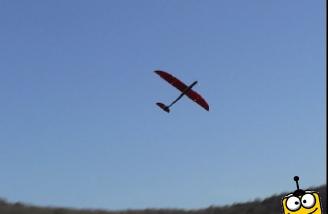
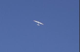
With this power system, the model came alive! It rocketed away from my hand, and I could immediately tell that it I would like this combination. It flew so much better - faster, of course, and could climb vertically, but it also retained energy and tracked much better than it had with the lighter battery. It felt like a real hotliner now, and I think it is apparent in the video clips. The landings were a little faster, but still slow compared to many hotliner class models.
At this point, the sun had set, and I had to pack her away. The performance was excellent with this combination, however, and although I will probably experiment with another prop (I have a narrow blade 12.5x13 I can try), I would be very happy staying with this combination. I also plan to see how she handles with a light setup, using the GP1100 packs, for thermalling, but that will have to wait until we get suitable conditions. I'll report in the discussion thread attached to this review.
Flight Video/Photo Gallery
MPEG VideoDownloads
Windows Media:Downloads
First flights
12.34 MB
Flight clips only
7.71 MB
Is This For a Beginner?
I would say this model would make a suitable first-model if the power is kept near the lower end of the suggested range, and an experienced modeler was on-hand able to check the model over, and help with the first few flights. Correctly assembled, it flies straight and level with virtually no trim changes, and as a glider, it really performs well. With a little coaching, a beginner could easily master launching and landing this model, and they would be able to practice both basic aerobatics and thermalling with it. Finally, as their skills improve, they could upgrade the power system and move into higher performance flying with the same model.
Conclusion
I had one of my earlier hotliners configured with a relatively low-power setup, and the light wingloading made this one of my favorite models. A lightly loaded hotliner does not retain energy as well as one that is stuffed with as much motor and battery as the fuselage can hold, but they can still be a lot of fun to fly. Most importantly, in my opinion, if you are flying a lot of faster models, it a good idea to have a lighter, less powerful model to warm up with. The Siren is by no means deficient in its design simply because it cannot handle a 1000W+ power system! Rather, I think the narrow fuselage and subsequent restrictions on how much battery you can install are a clever way of ensuring the modeler does not overpower this airframe. There was a lot of concern about the wing being able to handle "hotliner-style" flying - I pushed the limits with my last test flights, going beyond the 500W suggested limit, and flew the model quite aggressively. Although I did not deliberately attempt to destroy the airframe, I did fly it hard, and it suffered no damage as a result. It is most important to keep in mind the intended customer - an entry-level hotliner is appropriate for pilots who have some experience, and want to move into a different class of RC flying. That said, I think this model will appeal to the more experienced pilot too, simply because it is economical, easy to assemble, and fun to fly! I certainly plan to keep this one around, whether to warm up for more powerful models, or simply to enjoy for what it is! It is outstanding value, and appropriately powered by a brushless motor, is more than worthy of being called a hotliner. ImagesView all Images in thread
|
||||||||||||||||||||||||||||||
|
|
Last edited by AMCross; Jan 15, 2007 at 10:38 AM.
|
||||||||||||||||||||||||||||||


|
|
|
|
|
|
|
Ditto, good job Andy. Like the voice-overs on the vid! -thumbs
|
|
|
|

|
|
||
|
Thread OP
|
I received this email:
Quote:
The Kontronik motor I have in this model is probably somewhere in the 80% efficiency range at the power levels I am pushing through it. It's not a black and white issue, however. I did not intentionally attempt to destroy the airframe with violent manauevers. I flew the model in the style for which I see it being designed for (see video for my idea of how a hotliner should be flown). Hope this helps.. ..a |
|
|
|
||
|
|
|
|
|
Very good review - I purchased mine after reading the original and part 2 threads. While I am only up to 350 watts you have given us all sonthing to shoot for. In my case after reading the threads I bought one to use as a "trainer" for this style of flying and to even see if I would enjoy it. So far so good - I am hooked.
 thanks John |
|
|
|
|
|
|
|
|
Thanks for replying to my question about watts. I see that you are from Marietta, GA. You wouldn't happen to work for Lockheed would you. Unless I am totaly mistaken Lockheed has offices/factories there.
|
|
|
|
|
|
|
|
|
Yes... please spil. I am also interested?
|
|
|
|
|
|
|
|
Thread OP
|
No, I don't work for LMCO..
I changed out the provided ESC for a Jeti 70 I had laying around. The last setup I flew pushed the Kontronik hard, but I wanted to see how it would handle a tad more power - particularly pitch speed. I have RFM 12.5x13 thin carbon blades, and I tested them earlier. On the 10-cell CP1700 pack, about 55A on a half-charged pack, a tad more than 500W. Quite a bit beyond recommended power limits, but I can't see the power alone causing a problem. I don't fly crazy aerobatics, as you can see from the video, so we'll see.. I'll be flying it at SEFF this weekend.. ..a |
|
|
|
|
|
|
|
|
Hey ya'll,
I wanted to offer my input about the Siren. I am runnig an Aveox 2726/1.5 with a panetary gearbox at 4.28:1, Graupner Folding 13/7 prop, BB Model ALU spinner, PHX45 ESC and a Polyquest 3S2P 4000 lipo battery pack. Needless to say it has more than 1:1 power to weight ration. It will climb out vertical at 3/4 power and I can do more than 10ea 20sec. climbs. Anything more than 20 sec. and I cant see it. I have found that it will thermal but must stay moving a bit faster than my other sailplanes to stay in lift. So circles are a bit oblonged and not so tight. I love it. Have fun! RGG gci@charter.net |
|
|
|
|
|
|
|
Thread OP
|
Get a higher pitch prop and a larger ESC, if you want real fun. 20 seconds would put mine at about 1200' - most of my climbs are 5-7 seconds or so, and it moves out. Anyone see me fly it @ SEFF? Everyone who commented was impressed.. The GP guys had theirs, but they flew the same 10-cells on the same motor, but with a 13x7, their climbs were nowhere near the performance of mine..
..a |
|
|
|
|
|
|
|
|
Andy - did you ever fly it on the GP-1100 10 cell pack? I'm interested in thermal performance as well.

|
|
|
|
|
|
|
|
Thread OP
|
No, I planned to but never got around to it.
I can say that it thermals fine, however, as the GP folks were flying their on 10 cells in the B LMR sailplane contest @ SEFF. They made some good flights when they found lift. It came down like a stone when they didn't, however! ..a |
|
|
|
| Thread Tools | |


| Similar Threads | |||||
| Category | Thread | Thread Starter | Forum | Replies | Last Post |
| Great Planes Wright Flyer ARF Review | Michael Heer | Parkflyers | 25 | Dec 24, 2023 01:44 PM | |
| Sold | Great Planes Siren Hotliner ARF | Steve H. | Aircraft - Sailplanes (FS/W) | 1 | Sep 13, 2006 03:28 AM |
| Sold | Great Planes Siren Hotliner Sailplane | glide | Aircraft - Sailplanes (FS/W) | 6 | Oct 08, 2005 01:20 AM |
| Sold | Great Planes Siren Hotliner EP ARF 79" (NIB) | trw43 | Aircraft - Electric - Airplanes (FS/W) | 1 | Oct 03, 2005 07:20 PM |
| Great planes siren?? Hotliner or warmliner? | argarre | Electric Sailplanes | 3 | Sep 01, 2004 08:16 PM | |