|
|
|
|
|
Build Log
DW Hobby Griffin Build Log
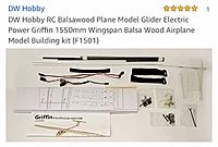
This is a build log for the DW Hobby Griffin 1501.The DW Griffin is a 1.55m (61”) balsa kit. Although I have completed two balsa builds, this is my first RC balsa kit.
The kit included: 1:1 folded plans, full-color instruction photo “manual,” laser-cut balsa and light ply planks, clear canopy, battery straps, dowel rod, control horns, servo extensions, motor backplate, and a bag of screws for the wing hold-down and joining the control horns and control rods. I paid $49 US on January 4, 2020. The plane was first released July 2016. It arrived from China unharmed (via Banggood) on February 5. Specs: 1/9 scale of something close to a B6-500 Elan Glider 46’ WS = 14 meters 1/9= 61.3” 24’ length = 8.4 m = 32” Griffin specs: Wingspan: 1550mm (61”) Fuselage Length: 820mm (33”) Flying Weight: 650g (1.4 lbs. or 22.9 oz.) Needed to fly: Motor: recommended 2212 1100KV ESC: 20A recommenced -- I'm using a 30A ESC Servo: 9g (4 needed) 8 inch Folding Propeller: (I'm using 9.25X7.25, Shaft 3.17) Covering: 2 rolls: Using 1 roll White Monokote and 1 roll black Econokote. Battery: 3S 1300 mAh 4 Channel Receiver & Transmitter — Spektrum AR410 Rx with a Spektrum Dx6e Tx. Photos attached are from promotional ads for the Kit. Permission to develop this Build Log was provided by Janna at DW Hobby. I received no compensation for this build or viewpoints made during the construction. |
|
|
Last edited by UpNup; Mar 15, 2020 at 04:39 AM.
|
|
|
|
|
|
|
|
The influence of Harley Michealis
Harley Michaelis and I met in 2019. Harley is now 99 years old. I tracked him down simply because of an email address remaining the same from an article in Model Aviation Mag, November 1989. Harley had developed a slope soaring glider that had twisty wings, called a pitcheron. The soaring glider was named Orca (Japanese for killer whale). A 2012 update exists. It’s actually a “hotliner” capable of 100+ mph speeds with no motor.
Harley didn’t have a copy of the magazine and so I mailed it to him. That act led to many email exchanges. Harley is a strong follower of Jesus and has had an amazing life. So, based on that experience, I have focused my next build — a t-tail glider. I live in Ohio so a powered thermal glider is a better choice for me. And that’s what helped me decide on the 1.55m (61”) Griffin balsa kit. In keeping with my approach to this hobby, I made a 1:48 scale plastic model. It had to be a scratch build since no model was available. I fashioned it after the DW Hobbies Griffin glider and used the design from the 1989 version of the Orca. I built the plastic model during the month it took to have the glider kit delivered from China. Harley and I keep talking. He really would prefer that I build his Easy Genie. I just might some day. |
|
|
|
|
|
|
|
|
Griffin Plan Review -- and Changes
The Griffin came with a five-page color description of construction.
These notes were made following construction. It is helpful to know them ahead of time. I wish I'd known! 1. Pages 1-2 seemed to be correct. 2. Page 3 There is a change that was made from the plans to the kit that involve a 2.5 Hex screw. These four screws hold down the wing. They require an Allen wrench not included with the kit. The plans show two screws inserted from below extending upward from former F15. F15 is not labeled in the plan. In a view of A1, the bottom sheet, there are two holes drilled in A1 shown in the plans that don’t exist in the A1 in the kit. That’s because holes had to be drilled to remove the hex screws. Only insert the hex screws from the top. They will eventually go through the wing into the fuselage. 3. The plan pages are numbered up to page 3, but not afterward. 4. On page 5, the kit comes with four washers that I recommend to be used to hold the motor to the motor mount. If you do, you’ll need to create four washers to use with the hex screw on the wings. These were easily made out of 1/16” styrene and painted. 5. On page 5, note that the servo extension wire comes out of the wrong hole. It must come out of the vertical rectangle on W21 or it will be outside the fuselage. 6. On page 5, the control horn on the aileron is not located in the correct position. The correct position has the holes over the gap between the aileron and the wings. 7. On page five, the Elevator horn should be reversed, pointing backward. This gives the elevator room to lower. Note that the angle of the control rod is too steep to be effective. Optimize effectiveness by channeling the tube with control cable into a forward position. See the Build Log for details. 8. On page five, The Rudder control horn is vertical and should be perpendicular with the holes over the gap. Wire should be angled outward from the fuselage and bent toward the fin. |
|
|
|
|
|
|
|
|
Getting ready to build
Everything was in English from the 1:1 plans to the manual to the characters. This plane could be covered clear and no ID marks would be on any piece. DW Hobby always places them adjacent to each part.
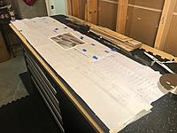
The 1:1 plans were folded and were difficult to lay flat. I placed books overnight on the open plans and with pushpins over wax paper, the flatness was acceptable. Put identifying marks on every piece of balsa and ply. DW Hobby put letters and numbers adjacent to each piece. I’m assuming this is if you want to use a see-through covering. Many of the laser-cut balsa pieces were jostled free from their planks. An ID on each piece that matches the picture manual will save time. The kit comes with a folded sheet that is nearly 6’ wide by 2’ tall. Expect it to cover the wings and elevator. But you’ll need the picture-based manual to figure out the tail. Highlights to note: There are circled numbers that mean nothing. Ignore them. Ignore the 1:5 ratio on the front profile illustration. This is closer to a 1:9 scale of the 46’ wingspan B6-500 Elan, if anything. Don’t miss W16 on the wingtips. It’s in the parts, but not on the plans. The plans don’t make note of control horn placement or the CA hinge placement. The hinges are pre-cut and those closest to the servos are in the way of the control horn. You’ll want to cut new ones. |
|
|
|
|
|
|
|
|
Building the Griffin Wings
The photos in the manual do not express two important points: (1) the wing could be built so that it can be slid together and stored in two halves and (2) the holes in the ribs were cleverly cut to ensure a 1 mm (approx. ½”) dihedral out on the ends of the wingtips.
My kit had a central carbon fiber tube that barely fit over the two outer, smaller tubes. I had to use a hammer to tap both smaller tubes in place. The right wing was built around the tube. I had to permanently join the wing halves. Once covered, the wing halves cannot be opened. ImagesView all Images in thread
|
|
|
|
|
|
|
|
|
Building the Elevator for the Griffin
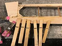
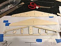
The elevator pieces are well-marked in the picture plan. I pinned the framework together using the “S” balsa pieces. There are two main holes and two tiny holes (horn) that must line up. They should also be cleared of any glue before it sets. The sheeting is about 1/32” thin, so gluing it could warp the whole frame. I used Titebond II as glue.
One simple hack is to lay a big book across the three layers and let them dry perfectly flat overnight. Make sure all the balsa is covered with equal pressure. UPDATE: It would be wise to lighten the tail by cutting through the sheeting after gluing it in place. It's easier to do here than later when covering film is in place. (!) |
|
|
Last edited by UpNup; Apr 27, 2020 at 07:05 AM.
|
|
|
|
|
|
Building Rudder and Fin on the Griffin
Begin the tail by building the boom. It has two formers that help square it up, but using clamps to ensure 90 degrees is helpful. Do not put the top on the boom until last (A16).
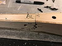
OPTION / MODIFICATION: It is recommended that you purchase two 3/8” carbon fiber slats and epoxy them just below where A16 fits on both sides. This provides lateral strength to the back in that the carbon fiber rod cannot provide alone. Refer to the plans and move A5 balsa doublers, gluing them in a new place just behind the first former of the tail boom. FIN: Begin the fin construction by gluing the leading edge to the left balsa sheeting. Follow the plans and place the three ply pieces in place and then the left (rear) ply piece. OPTION/ MODIFICATION: Reroute the plastic tube and control wire. Use a power tool to carefully cut a channel. Refer to the plan detail from the Carl Goldberg Sophisticated Lady glider. It, too, had a T-tail. To mirror this path, you’ll need to curve the plastic tube provided with the kit. I did this with a heat gun and then epoxied it in place. I also slipped graphite dust into the tube to ease friction when the control cable was in motion. NOTE: While examining the SL plan, note that the control horn on the elevator is reversed to provide more movement. Remove the bottom 1/8” of right balsa sheet. Also use your power tool to carefully cut a trench so that the right sheet fits flush with the LE and TE of the fin. ROD: The rod comes with a useless slit, which can be ignored. You’ll need to cut your own slit on the top of the rod for the elevator wire and one on the side for the rudder wire. Save the powder and slide it into the tube of the elevator control tube to reduce friction. UPDATE: Go ahead and cut out the center of the sheeting for the stabilizer and the whole rudder center before covering. You'll need to do this anyway to lighten the tail. Note that the stab is 3/8" thick, so you'll need to add some supportive balsa sticks. |
|
|
Last edited by UpNup; Apr 27, 2020 at 07:07 AM.
|
|
|
|
|
|
Finishing the Tail Boom on Griffin
Glue the pieces together to form the rudder and T-tail with elevator. Note that the lines have been drawn in advance in case it’s necessary to lighten the tail substantially.
The kit is relatively complete, so it was surprising that several elements were missing: You’ll need 5/8” wood flat head screws came to attach the empennage to the fin. It helps to drill out the holes to keep the wood from splitting. Plan on cutting CA hinge slots into the T-tail left to right at 2 ¼”, 5”, 8”, and 10 ¾”. Control rod cables are all that are provided. You’ll cut the rods to fit the servos in the fuselage. Save those cuttings to use in the control rods on the wing servos to control rods. It helps to bend the wire going to the rudder so that it pulls straighter. Expect to cut off screws used with all the control horns. Finish the tail by gluing the top slat A16 in place. The photos in the manual have some glitches that you’ll want to correct: a. The rudder’s control horn in the photo is placed vertically. It needs to be sideways to be more aerodynamic and better facilitate the action of the control wire. b. The aileron control horns are shown in the middle of the aileron. The side with the holes need to be on the gap between aileron and wing. c. The number of holes in the sheeting and body are for lightening the frame. The illustrated manual leaves them alone. Since they’ll be covered, it helps to cleanly remove them. Run the wires sticking from the control rod into the fuselage and then mate the two flat formers. Use five-minute epoxy and pins to glue the joint. Keep the joint flat and the back end perfectly level. Use a 90 degree triangle to ensure accuracy. UPDATE: Note the lines crawn on the stab's sheeting. Go ahead and cut out the sheeting and add sticks to lighten the tail. |
|
|
Last edited by UpNup; Apr 27, 2020 at 07:09 AM.
|
|
|
|
|
|
Options on Griffin' Tail
OPTION: You can make a rolled-ply Leading Edge for the tail fin. Soak 1/32” light plywood sheet (not with the kit) until it can be rolled around a dowel rod – approx. ¼” in diameter. Use rubber bands to hold the ply in shape and let dry overnight. Cut the ply “tube” in half. Sand flat the portion going against the LE and glue.
OPTION: You can make supports for the stabilizer. Use scrap balsa ¼” X ¼” balsa sticks or triangle stock. Sand the lower portion to help the air flow. Glue to the side of the fin. Sand lightly to match the top of the fin and make a wider platform upon which the stabilizer rests. OPTION: Carefully sand a taper on both sides of the Trailing Edges of the Rudder and the Elevator. Leave the ends at least 1/16” thick in the middle. Tape down a sheet of sandpaper and move the entire surface to make sure there are no flat spots. Not shown is to sand a curve into the leading edges of the ailerons, rudder, and elevator. This is make them swivel better when the CA hinges are in place. UPDATE: Cut out the rudder's center and add sticks for support. This is to lighten the tail. (Do not do anything to the elevator.) |
|
|
Last edited by UpNup; Apr 27, 2020 at 07:10 AM.
|
|
|
|
|
|
Canopy for Griffin
The canopy was trimmed to fit the fuselage. It is not very aerodynamic and it is difficult to make stick to the glider.
Options are underway. See the end for Finishing Details. |
|
|
Last edited by UpNup; Mar 14, 2020 at 03:41 PM.
|
|
|
|
|
|
Building the Fuselage for the Griffin
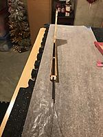
The fuselage is almost impossible to build over the plan. Think of the fuselage as a 3D jigsaw puzzle. I started with the F8 former and clamped them into right angles. Note that the use of wide blue painter’s tape provides an extra clamp throughout the build.
Build the core of the fuselage first. Remember to keep those hex screws inserted from the top down. In my photos, I was trying to follow the DW Hobby guide and it just wasn’t correct. The nose of the Griffin is easy to assemble. However, I’d recommend inserting the motor mount prior to installing the F1 former in the front. The motor only mounts in one direction. Know this before inserting it. And do it after F2 & F3 are in place to save time. As I mentioned earlier, I chose to use the four washers to secure the motor mount. I also used (red) Locktite for screws to help them set. |
|
|
|
|
|
|
|
|
Installing Electronics in Griffin
The electronics in the glider are typical for a 4-channel RC plane.
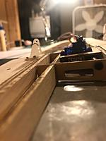
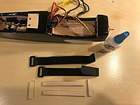
Install the servos on the bottom of the wing. They stick up and can’t be laid sideways because of the carbon fiber rod. Use leftover wires from Rudder and Elevator on wings. There are holes in the ailerons that came with the kit that must be avoided to ensure the control rods work correctly. Run the wing-mounted servo wires through the aileron holes toward the middle. The kit comes with extension cables. Cut 2” sections of heatshrink tubing and slip them on to the cables prior to making the connection. Then use a heatgun to help the connectors remain firmly in place. Use the Y Connector that came with the kit to link the cables coming in from the wing servos. These will plug into your plane’s receiver (Rx). The Rx will recognize this as one servo, but splits their action. Install all the electronics and test. It is recommending that all testing done have the folding prop removed from the motor shaft. There are two black hook and loop straps that apparently were to go into wood formers in the cockpit. The formers were not included, but the holes remain. ImagesView all Images in thread
|
|
|
|
|
|
|
|
|
Covering the Griffin
Prepare the surface for covering with film. Lightly sand one final time and fill in gaps with a lightweight filler (spackling). Wipe everything down with a lint-free cloth and alcohol. Now is also a really good time to clean your bench to be free of dust and any stray bits that could get under the film.
Cover the glider with film. I used white Monokote and black Econokote. The Econokote is a low heat film that works great as an accent graphic over high heat Monokote. Use an iron to seal the edges, then a heat gun to stretch the film tight. The following order of covering helps the airflow not peel the film when in flight: 1. Cover the underside of the wings in four parts – wingtips to servos, then to the middle. 2. Cover the top of the wings in two parts – wingtips to middle 3. Cover the ailerons, bottom first, then top. (Use a piece of tape to mark where the CA hinge slits go.) 4. Cover the Elevator, Empennage, and Rudder. Lay down strips at the top and bottom of the fin so that there are no gaps when the side pieces go on. 5. Cover the fuselage from bottom to top and back to front. The very front is boxy and requires care. DO consider putting reflecting chrome panels on your wingtips to catch the sun during turns. DON’T do what I did. I made two ailerons exactly the same. Only when I was gluing the CA hinges in place did I discover my mistake. My kit only had four washers and I used them on the motor nuts. I made my own washers for the wings and empennage out of polystyrene 1/16” plastic. While I was at it, I made two additional washers to use with the screws -- that did not come with the kit -- to hold down the stabilizer to the fin. ImagesView all Images in thread
|
|
|
|
|
|
|
|
|
Making a Cockpit brace and floor on Griffin
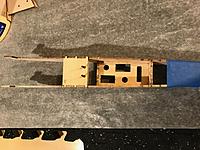
You'll need to make a retaining system for your cockpit electronics. The walls include cutouts, but evidently DW Hobby abandoned the idea. However, the kit included two straps.
Use five 3/8” ply strips or popsicle sticks glued with CA or 5-min. epoxy to the floor of the cockpit to keep everything in place. Put the three crossbars in first right to the cockpit floor. Put the straps in place making sure the hook and loop goes the right way. CA the two long strips on top of the 3 crossbars over the straps. One cool tip is to put your 2.5 Allen wrench in the L-shaped hole in the wall. It's held in place by the straps on the buckle side. |
|
|
|
|
|
|
|
|
Setting Up Your Tx for a Sailplane
The Griffin depends on electric power. This Transmitter (Tx) set-up is for a Spectrum Dx6e. It may be helpful with other remote control devices as well.
My appreciation goes to Spektrum Support who worked through this with me. REMOVE YOUR FOLDING PROP BEFORE ADJUSTING ANY SETTINGS. Set up your Tx for a Sailplane. The controls are somewhat different from other options. If you use the Y-connector for the Ailerons included in the kit, then select the “1-Servo” option. Both ailerons will work properly. Choose “Normal” for Tail since you have an Elevator and Rudder. Choose “Thr. Stick” for Motor. Select Throttle Cut to work on the A Switch. Push the Throttle Trim button down and hold it until you get to -130%. Use Switch A (or some other switch) as your cut level. I chose Switch A because it’s a toggle switch on the back left side. Make sure your Rx (Receiver) Port Assignments are in alignment. I used the new Spectrum 4-channel Rx. BATT is empty. 1: Throttle (plugs into your ESC) 2: Aileron (Y-connector to both) 3: Elevator 4: Rudder Note: Should your motor run in reverse, switch wires from your motor to your ESC |
|
|
|
«
Previous Thread
|
Next Thread
»
| Thread Tools | |
| Similar Threads | |||||
| Category | Thread | Thread Starter | Forum | Replies | Last Post |
| Build Log | Construction and Build Log - Griffin Trainer Kit Build | soarus_1999 | Electric Plane Talk | 47 | Jul 09, 2007 10:49 PM |


