|
|
|
|
Thread OP
|
Discussion
Frogfoot
As promised here - https://www.rcgroups.com/forums/show...3&postcount=42 - I produced and tested the ducting and now intend to build the Frogfoot around it.
The ducts are fibreglass formed on planked balsa moulds. The flanges are liteply 0.6 mm. I wish I could 3D print, I am not 100% happy with the quality but it works. The measured thrust with the full ducting is 370 g, as compared with 330 g for the "bare" EDF. The diagrams for thrust vs. RPM, and thrust vs. input power are shown below. However, I am not going to discuss the measurement results now. As my target value for continuing with the Suchoi was 80%, and reached 110%, I am now committed to building it. The model is going to be loosely based on the Frogfoot, I have no intention to build it to exact scale. The wingspan is about 760 mm (30"), expected AUW is 360 g (13 oz). The drive is Hobbyking 53 mm/5 blade EDF with 4800 kv inrunner, supplied from 3S1000 via 22 A ESC. The drive train with the ducting is 220 g, so there remains about 100 g for the airframe, hopefully doable. Jan ImagesView all Images in thread
|
|
|
|


")
")
|
|
|
|
|
|
|
Jan, that is incredibly nice molding work! You know what your doing, so I will silently watch.
Fuzz |
|
|
|
|
|
|
|
Thread OP
|
Thank you, Fuss.
I think I over-engineered the ducting - spent two days writing a program for geometry generation, then drawing, mold fabrication, fiberglassing, sanding, mating,... I think I could have a small model completed in that time  . But the ducting works suprisingly well, which is a good feeling. . But the ducting works suprisingly well, which is a good feeling.Now I am at design work on the airframe and compromising the scale factor with every line drawn, my hat off to all who could design true scale models. Jan |
|
|
|

|
|
|
|
Thread OP
|
Duct data calculation
I am afraid this will not interest many people but my line of thoughts was as follows:
1) The inlet intakes of the Suchoi seems to be formed by two semicircles with an rectangular insert. 2) The ducting is symetric along the horizontal plane each half of the duct cross-section can be composed of two circle qudrants (with radii r1 and r2) and two rectangles (with heights h1 and h2) 3) There are thus 4 unknown variables, only 3 are independend as r1+h1=r2+h2, so I needed 3 additional (arbitrary) rules for definition: - duct height changes linearly along its length - duct cross-section changes linearly along its length - radius r2 changes linearly along the duct length (I tried also other combination of rules, including the minimalization of the wetted surface, but the differences are very small) 4) Cross-sections at various stations were thus defined and calculated 5) Next step was the duct S-shape axis definition. After testing several different curves I ended up with a simple polynomial of degree 3. 6) Eventually, the duct cross-sections are "placed" over the S-shape axis. Based on the generated data I drew the parts for the duct moulds. The EDF has a large diameter of 53 mm, small diameter of 21 mm. The inlet duct thus has 125% FSA at intake, and 119% at EDF. The outlet duct then contracts from 119% at EDF down to 90% at exit. Hope this make sense. If anyone is interested in the calculation excel sheet, please let me know. Jan |
|
|
|


|
|
|
|
|
Hi Jan, not having the tech know how as yourself, I have to resort to figuring intake/exhaust areas, then physically blending them in the middle with the shaping of the plug. It has worked over the decades. But , one problem I have is being able to fully explain what I did! I know the requirements needed for a lot of fans. So, I guess that helps a lot.
I have made glass ducting for D/F from the Byron days of the early 80's. FSA, was not in my vocabulary back then. But, I knew no fan was the same as another in it abilities or requirements. A lot of so-so results till I got it right. All the time, the real barrier was not understanding that the area of the fan was the blades only... Fuzz |
|
|
|
|
|
|
|
|
Your approach is quite clear and it looks like you have it down, more than me! I tried creating ducting in CAD but I could never get the FSA truly continuous from intake to the fan. I guess it makes sense that you scale each geometric element individually - at least, that is what it looks like. It’s enjoyable to see someone working the science of ducts properly (there are so many misconceptions). To be clear, I think I know the theory, I’m just terrible at implementation :P
|
|
|
|
|
|
|
|
Thread OP
|
Thank you, guys, for your kind words.
Fuzz, experience always helps a lot, but mine is very limited in the EDF field, the Suchoi is going to be my third jet (not counting two foamies). I think that with your proficiency and building speed you would be flying by now. Jan |
|
|
|
|
|
||
|
|
Quote:
Jan, your getting a good start, you will grasp is all much quicker than I did. Fuzz |
|
|
|
||

|
|
|
|
|
I found that it was possible to print a bifurcated inlet although in my case for a 50 mm EDF with a single exhaust.
For geometric simplicity the inlets are plane half circles. The duct is the diameter of the EDF body giving nearly 1.2 the FSA  Of course two 1/2 circle ducts have greater losses than a full circle so the length of bifurcated section was kept reasonably short. Due to bed size limitations the duct is in 4 pieces glued together. The duct is printed as a single wall 0.25 mm thick. The EDF had no bell mouth and delivered 340 g thrust stand alone in free air on a 3s. With sharp edge inlets the full duct reduced this figure to 311 g. With the addition of a small radius printed bell mouth close to a scale size. 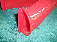 The thrust reached 326 g. Just as an aside the reason the EDF was set right at the back to give an "annular" exhaust was the out runner motor bell was larger that the fan hub.  This meant a constant diameter duct gave 120% FSA inlet and 90% FSA exhaust. |
|
|
|
|
|
|
|
|
Having the bifurcated intake converge that far in front of the fan, is causing turbulence. With a bifurcation, it is best to have two separate ducts, right up to the fan. Each side of the fan recieving it's own flow. The vertical flat section of the duct is radiused to clear the rotors spinner. In cases where the two ducts are spaced up to the fan, this spinner clearance provides a vent, to make the fuselage a low pressure area, for cooling flow. One benefit of a bifurcated intake. If not clear, I can dig up some pics.
Fuzz |
|
|
|
|
|
|
|
|
I think Quorneng got it right, “Winmodels” has done an incredible amount of research and he proposed the same solution.
https://www.rcgroups.com/forums/show...20&postcount=3 |
|
|
|
|
|
|
|
|
Sorry, but your comparing an exhaust duct to a intake duct.
|
|
|
|
|
|
|
|
|
St.Martin
I agree where a bifurcated section merges into a single duct it is likely to create extra turbulence losses but a bifurcated duct with two half circle ducts has close to 60% more surface area and top and bottom sharp corners as well. Conventional duct theory indicates that such a section would have significantly greater losses per unit length than a circular duct of the same area and with two such ducts the losses would greater still than a single duct of their combined area. How long the bifurcated section should be then comes down to whether the 'merge' losses are greater than the bifurcated duct losses. One advantage of CAD and 3D printing is the bifurcated inlet can be designed to give the best possible junction geometry. 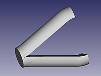 My own experience suggests the 'merge' losses on a well designed duct junction are much lower than the losses due to the length of bifurcated duct. |
|
|
|
«
Previous Thread
|
Next Thread
»
| Thread Tools | |


| Similar Threads | |||||
| Category | Thread | Thread Starter | Forum | Replies | Last Post |
| su-25 frogfoot | Robbie d | Electric Ducted Fan Jet Talk | 7 | Dec 03, 2009 11:02 AM | |
| Sukhoi 39 Frogfoot | Neil Straker | Pusher Prop Jet Models | 108 | Sep 14, 2005 10:15 PM | |
| Frog legs?? naw I'll have a Frogfoot | Dragon Soaring | Slope Soaring | 18 | May 15, 2005 01:34 PM | |
| EDF50 SU25 Frogfoot | jah | Electric Ducted Fan Jet Talk | 46 | Mar 26, 2002 07:11 PM | |