|
|
|
|
Thread OP
|
Windows, Stabilizers, & Rear Wing Attachment Installation
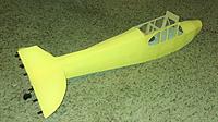
The windows are now permanently glued in. I filled around the edges where the balsa window frame and the DTF meet with some of the lightweight spackling and then sanded smooth. I also went ahead and filled in all of the joints where the tabs of the formers lock into the fuselage skins. I then sanded these down, and added a coat of paint.
I also glued the horizontal and vertical stabilizers together. I used a speed square to make sure I got a nice 90 degree fit. I then glued the tail assembly to the fuselage. From there, I took a quick detour and finished up the basswood brackets that will attach the aft side of the wing to the fuselage, As can be seen in the pictures, these brackets have nuts glued into them, so that nylon screws can be threaded in. The last picture shows these brackets installed. I did modify these brackets from the plans. In the plans the aft wing attachment uses only one nylon screw, but I modified the bracket to use two nylon screws instead. |
|
|
|
|
|
|
|
|
|
Thread OP
|
Turtle Deck
The turtle deck is now glued on. I used some painters masking tape to help hold the turtle deck in place while the glue was drying. I also added some fairings around the intersection of the horizontal and vertical stabilizers.
|
|
|
|
|
|
|
|
|
so much awesomeness
|
|
|
|
|
|
|
|
Thread OP
|
Tail Control Surfaces & Brace Wires
The tail control surfaces are now glued in. Attaching them was just a matter of cutting slots to line up with the floppy disk hinges, adding some glue to the hinges, and then sliding the surfaces onto the hinges. As you slide the surfaces onto the hinges the glue has a tendency to pile up outside the slot, so you need to be ready with some q-tips (or something) to wipe away the glue so that it doesn't bind the surface to the stabilizer.
After the surfaces were glued in, I installed the push/pull rods that go between the servos (standard 9 gram servos) and the control horns. The rods are 1mm diameter carbon fiber rod. On the servo end, a z-bend paper clip is glued to the rod by wrapping the attachment with thread and then epoxy-ing in place. This creates a very strong joint. On the control horn end, a plastic clevis is epoxied to the rod. This method doesn't have a lot of adjustability for mechanical trimming, but I'm thinking that I will likely have enough trim digitally in the transmitter. You may notice that the push rods run through fairleads in the formers. These fairleads are made from the spray tip of a WD-40 can. They help reduce friction in the system, and they will protect the foam from wear. They also serve to reduce the effective buckling length of the column when the rod is in compression during the "push" operations. With the control rods connected, I attached the flying wires (which are also made from the same 1mm diameter carbon fiber rod). The stabilizers already feel very strong, but these flying wires still help to add to the scale detail. A final touch was to add a decal of the cub logo on the vertical stab. This was simply done by printing off the logo, cutting it out, and then gluing it down. |
|
|
|
|
|
|
|
Thread OP
|
Wheels
I'm glad you're enjoying the build Jim!
I'm taking a little break from the fuselage today, and working on the wheels. The tires are made from 6 circles of laminated DTF. The outer two layers are donuts to give the nice bush tire look. After the layers were glued together, I used the exacto and some sanding to remove the "steps." After the shaping the wheels, I cut a black balloon and wrapped it over the foam. I then cut a second balloon and wrapped it from the other side. After both sides had been wrapped, I made a hub from bass wood and glued an axle bushing to it (WD40 spray tip). I then put some glue on the hub and the bushing and pressed it into the wheel. The axle bushing protrudes all the way through the wheel, so I then capped it with another hub on the opposite side. It's a pretty simple method, but it creates a killer looking tire. The nice thing about this method is that you can create tires of any size you want. The rest of the landing gear should be up tomorrow. |
|
|
Last edited by Plane15; Sep 25, 2018 at 12:19 AM.
|
|
|
|
|
|
Hi,
Great job on this build and very original idea for the build of the J3's wheels. Some pictures of the wrapping process could be very interesting imho. Will they be trong enough to resist to some hard landings ? Have a nice day ! |
|
|
|
|
|
|
|
Thread OP
|
"Will they be strong enough to resist to some hard landings ?"
Great questions guys. First of all, hard landings? What are those?  But more seriously, yes, these wheels are very tough. Don't be deceived by their delicate appearance, the foam is quite strong when laminated. Elewon's comment about abrasive wear on pavement would be more of the concern. This is primarily addressed by the wrapping technique. By wrapping the wheels from both sides, the outer diameter of the wheel gets covered twice, making the rubber twice as thick where the wheels actually make contact with the ground. Also remember that the rubber is not stretched super thin, just enough to get the wrinkles out. I guess time will tell how they well hold up. I'll be sure to report back on their durability and maybe even do a more detailed how-to if enough people are interested. I mostly fly from a dirt/grass strip, and I have a feeling they will have no problem. Although, honestly I think they will probably handle pavement no problem also. My primary concern with the wheels was actually related to bearing failure at the contact of the foam with the axle. I addressed this by using the plastic bushing. This increases the bearing area of the joint, reducing the stress in the foam during impact. |
|
|
|
|
|
|
|
Thread OP
|
Bungee Gear
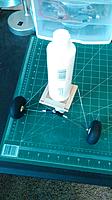
On the topic of landing gear, here are some shots of the bungee gear assembly. It uses .047" diameter spring steel wire bent to the template shown on the plans. Note that each side is made from a single length of steel. The bent landing gear legs mount to a bass wood platform where they are hinged and free to rotate. Some rubber bands act as the "bungees" that will help absorb landing loads. The imitation bungee covers were made from the grip of a mechanical pencil.
The axle nuts were made from some small plastic beads that I painted metallic to complete the look. These beads were then epoxied onto the axle so that the wheel would be captured. The wheels rotate nice and freely on the axle. I think I will also likely add a safety-cable to the bungees, like you often see on PA-18s. This will help limit the total travel of the gear. |
|
|
|
|
|
|
|
|
Nice job on documenting the build of the wheels and landing gear! I like that entire set up and would love to adapt that to use with my BB42.
|
|
|
|
|
|
|
|
|
there used to be quite a large CUB only event over at Mollala OR.
Your are doing such a great job of SCALING this model out ! You might want to consider looking them up. |
|
|
|
|
|
|
|
Thread OP
|
Landing Gear Install
The landing gear is now installed.
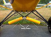
I started off by building the strut attach brackets. These brackets are made from some old plastic gift cards. They run through a cut in the side of the fuselage skin and are then glued to both the landing gear base and the landing gear doubler pieces. I attached an old photo from earlier in the build where I show the landing gear doubler pieces. The doublers are glued to two areas of central structure: the forward wing attach former, and the sidewall of the fuselage skin. The vertical landing loads will be reacted by both the former and the large area shear joint between the doublers and the skin. The horizontal loads, which will place a moment on the landing gear base will be reacted primarily by shear in the aft doublers. I also went ahead and glued in some imitation fuselage tubes in the windshield area. These are non-structural. They are made from rounded balsa, and then painted black. Scale Cub enthusiasts may note that they are actually pointing the wrong direction for a J3. Typically, these tubes point outboard from the center of the spar carry-through. On this build, the tubes point inboard, more reminiscent of a PA-18. I did end up installing some safety cables on the landing gear to limit the total deflection. The safety cables are made from nylon fishing line. I've attached an image for reference in case anyone was wondering what landing gear safety-cables looked like. |
|
|
|
|
|
|
|
|
Really like these wheels. What did you use to cut the DTF circles?
|
|
|
|
|
|
||
|
|
Quote:
great build, I love the creativity! |
|
|
Latest blog entry: shifting gears, selling some of my...
|
||
«
Previous Thread
|
Next Thread
»
| Thread Tools | |
| Similar Threads | |||||
| Category | Thread | Thread Starter | Forum | Replies | Last Post |
| Build Log | 1/3 Scale Piper J3 Cub from Paolo Severin | killerbob | Giant Scale Airplanes | 67 | Sep 04, 2018 09:50 AM |
| Discussion | Parkzone Sport Cub Vs. FMS J3 Piper Cub | RcMetal | Electric Plane Talk | 8 | Apr 07, 2016 05:46 PM |
| Discussion | Preguntas sobre peanut scale, Piper Cub J3 Peck-polymers. | banano | Mexico | 31 | Jun 07, 2010 06:55 PM |
| J3 Piper Cub 120 - 91" Engine Powered Scale NIB CMP aircraft | dealinrc | Other Websites | 0 | May 31, 2008 11:45 AM | |


