|
|
|
|
|
Once concern with moving the gear outboard is that the wings start to thin out and there is less material for the retracts to mount into. I'd have to modify the airfoils to be thicker to be able to properly support the span between the landing gear and the root. Additionally, the tilting of the bogie doesnt work with this, so it would need to be perpendicular to the struts.
Playing around with the model, I am leaning more towards keeping the landing gear location, but deepening the gear bays. I can probably alter the struts to be less scale and get a bit more compression travel as well. Currently I have about 20mm of travel on the struts . I would need to test out various springs to get the right amount of pre-loading when the plan is set on the ground. |
|
|
|
|
|
|
|
|
|
|
Chris,
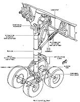
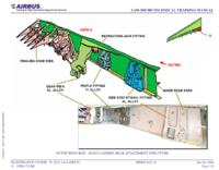
The full sized shortening mechanism does actually give us some grief occasionally. The shortening link has been known to snap, but the LGCIU has an input from a sensor which then stops the retraction cycle so as to not cause damage or jam up the gear. net result is an AOG aircraft at some random port or you ferry the A/C back home gear down. In the fullsized, the shiney chrome bit that we would normally associate as the sliding portion of the oleo is actually the sliding piston for the shortening of the gear. For retraction, have you thought of using an electric gear door actuator to move the gear themselves? would allow you to design slimmer gear pivot area/design into the wing structure, and potentially Then you could place the actuator flat against the wing surface ala B767 or 737. https://hobbyking.com/en_us/turnigy-...-120-size.html The actuator placement of the real A330 seems bewildering at first glance, because it uses brute force with very little mechanical advantage, but it is a very slim installation, and uses a bit of engineering brilliance (in my mind) to transmit none of the brute retracting forces to the airframe at all. It sits paralleled to the upper portion of the oleo Let me know if you want some pic's to explain further. they are worth 1000 words. I think they might give you something to base your designs on if your looking for some inspiration |
|
|
|
|
|
|||
|
|
Quote:
Quote:
I'm ok without pictures since I'm probably going to try for a 737-ish approach with the mechanism. Always great to listen to your insight on these aircraft  . .
|
||
|
|
|||
|
|
||
|
|
I think I settled on a main landing gear configuration. I feel as if the pitched bogie can be beneficial with dampening the landings, so I want to incorporate it into the geometry. My idea will be to add a spring in the front of the bogie where the pitch trimmer resides, so that on initial impact it will stretch and absorb some of the landing energy while the bogies settle onto the runway. It may be a fairly insignificant amount, but every bit can help.
With a 10 degree pitch, they are able to clear the gear bay, and not throw off the scale look of the gear bays too much. I also made progress on the flaps and hinging. For the inboard flap, I will need to design a type of hidden hinge that goes into the fuselage. Quote:
 . I'll model them in CAD when they arive and also see how well they fit in the wings. . I'll model them in CAD when they arive and also see how well they fit in the wings.
ImagesView all Images in thread
|
|
|
|
||
|
|
|
|
|
I got a fair bit of work completed on the wings the past few days. 700mm worth of wingspan is on the printer and I will have it welded up by tomorrow evening.
I also have some ideas for the hinging of the inboard flap. The inboard hinge could be concealed inside the belly fairing, but would need to be accomplished one of two ways: 1. The inboard flap can have a pin, that when the wing is attached, will need to be aligned with the inboard hinge. Problems I see with this would be that the inboard flap will be delicate whenever the wing is not connected. Also, it might make wing attachment more complicated. 2. Another option would be to have a small section of the belly fairing be a part of the detachable wings. This way the inboard hinge will be a permanent assembly. Less complicated, but might take a bit more effort to design. Of course, I can go simple and just add an external hinge on the wing. ImagesView all Images in thread
|
|
|
|
|
|
|
|
|
Hey Bud.....I think your best bet will be the external hinge for this application. Looking Good...!
|
|
|
|
|
|
|
|
|
Thanks! And yea, I think an external hing will be the best for this.
I was able to finish the outer 2/3rds of the wing test section this morning. While this was still printing yesterday, I already had some changes being added to the model. The unsupported sections between the forward and rear spars isn't much of an issue towards the tips, but when the gap gets wider than 75mm, the parts start to get a bit of "tin-canning" and start buckling in and out with a light amount of force. I've added a central spar from the root to the aileron servo hatch to take care of this. Giving the wing section a bit of flex with my hands, it is stronger than the wings on my foam ERJ. I don't think an internal carbon spar is really needed for the outer section of the wing. I may experiment with adding a 1 inch strip of fiberglass on the top and bottom of the wings just to help under high wingflex situations and prevent a catastrophic failure if the wing were to split along a layer line. Edge lifting from the print bed can be seen along the section joints, and is very visible at the spoilers. I will need to add some "feet" to these spot when printing to reduce the amount of curling. Thinking about navigation lights, I really like the CREE style LEDs that I used on my A-10 build, as they are very visible and give a good strobe action. But they are on the big side, and with a very narrow wingtip I may not be able to use them here. I may need to use more conventional LEDs at least for the wingtips. |
|
|
|
|
|
|
|
|
I LOVE how your wing is turning out especially the slat area. My friend and I just invested in a printer for RC quads and airliners so your build here is valuable to my research.
|
|
|
|
|
|
||
|
|
The Leading Edge Slat DilemmaQuote:
Though on the topic of slats, I have been dealing with conflicting feelings about the LE Slats the past week. A part of me really wants to implement them, but at this scale and with this skinny of a wing, it seems like it might be more problem than worth. The flaps and spoilers might even need to be operated with torque rods and bell cranks, as sub-micro servos are just barely small enough to fit inside the wings without sticking out. I have some ideas in mind to operate the LE Slats, including the use of springs to hold them shut and servo linkages to not cause binding when stowed or deployed. But, with the expected weight increase of ~120g for the LE slats, I wonder if the aerodynamic benefits will outweigh the AUW increase. I do want to do LE Slats on an airliner, but i'm thinking the scale needs to be a bit bigger to make it less complicated. I have plans to eventually make a 777 or 747 somewhere between 7-8ft wingspan down the road after I work on some smaller projects, so those might be better suited for the LE Slats. |
|
|
|
||
|
|
|
|
|
Some more progress with the wings. I am mostly settled on a spar design, but still need to add more reinforcement for the landing gear and nacelle pylon attachment. The wing will attach to the fuselage with a 10x8mm forward Cf tube and a rear 8x6mm CF tube. Like the tail, I will add two spots for attachment tabs to secure the wings with screws/bolts. Embedded in the center wing spar will be a ~500mm 8x6mm CF tube.
Hoping to begin printing the new test parts this week. I have merged the LE slats back into the wings already, but I still need to add panel lines to the wings to trace the shape of the LE slats for aesthetics and to help with painting. |
|
|
|
|
|
||
|
|
Quote:
The A330ís have neat flight controls. Ailerons droop with flap extension, rudder can compensate automatically for engine failure, etc... There is a cool YouTube video of an engine failure on the take off roll, and you can clearly see the rudder kick over. Anyways, if you ever need some detailed pictures of anything, let me know. Daren |
|
|
|
||
«
Previous Thread
|
Next Thread
»
| Thread Tools | |
| Similar Threads | |||||
| Category | Thread | Thread Starter | Forum | Replies | Last Post |
| Discussion | 3D printed 120mm EDF - 3D printed 1:6,5 scale L-39 | Lynxman | Large EDF Jets | 3352 | Apr 04, 2024 01:37 PM |
| Help! | A330-300 Scale Scratch questions | ahhmino | Scale Kit/Scratch Built | 2 | May 02, 2016 09:58 PM |
| Help! | A330-300 Scale Scratch Questions | ahhmino | RC Airliners (Commercial, Cargo, Troop Carrier) | 3 | Feb 21, 2016 04:45 AM |
| Build Log | Delta Airlines Airbus A330-300 | Rcflyyer1 | RC Airliners (Commercial, Cargo, Troop Carrier) | 22 | Nov 01, 2012 09:21 PM |


