| Thread Tools |
| This thread is privately moderated by TDisaster, who may elect to delete unwanted replies. |
|
|
|||
|
Thread OP
|
Discussion
Tracker III Repair Thread
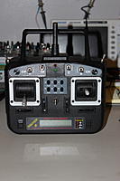
**neons** hooked me up with a Tracker III radio and two Seeker II receivers for free. The transmitter has an issue where the output is fine until roughly the last 1/4 of the stick in which it kicks back to center. It's showing this on both gimbals and all four channels, so the first step is to pop it open and measure the outputs of the gimbals to verify if they're the root of this problem. Seeing as all four channels are showing this behavior, odds are it's not the gimbals themselves, but I've seen weirder things happen. Below is a video showing the problem.
I'll be updating this post as I go through the repair. I've got some other work to fit in along with this, so it may be a few days before we see a working unit. |
||
|
|
|||
|
|
|
|
|||
|
Thread OP
|
Great case design on this radio. I've had a few radios in the past where switches were either mounted in the back plate, or left free to wander when it was removed. Removed one small JST connector for the trainer port and the back was totally free.
Once I had the radio open I removed the RF shield and trim pot screws to access the board that the right gimbal pots attached to. Probed those leads directly and everything checked out fine. Totally within tolerance and no weird bumps or jumps in the range.
The weird bounce in the servos leads me to believe we've got a power output issue. This jump happens on all channels when the stick heading towards the position where the resistance across the pot is lowest, so we may have a bad regulator...? It'd explain the jump to full opposite stick as I'm assuming the voltage across the pot is dropping as that current increases. I also found some solder joints that were in pretty bad shape on the menu board. Playing with the radio earlier I didn't get a response from the menu buttons when pressed, but I also haven't read the manual on operation, so it may just be user error. Regardless, I should be able to re-flow the joints with some hot air and clean it up without having to dig too deep. If these are shorted, it may be a part of the servo output issue. Next up is to check the pot outputs with power applied to the radio, but first I'll have to charge the camera. 
|
||
|
|
|||
|
|
|
|
Thread OP
|
Trimmed, stripped and re-soldered the wires to the menu button board. Also coated with some RTV for strain relief... not super clean, but my syringes are still in a box somewhere after the move and I didn't feel like digging.

|
|
|
|
|
|
|
|
Thread OP
|
So, after breaking down the radio it seems the issue lies on the main board. The odds of both multiplexers going bad seems extremely unlikely, so it seems that the PIC has failed in some way. I can source the PIC18F4620-I/PT chip, so that's not an issue... however, finding code seems very unlikely. There's an EEPROM on the main board as well, but I'd assume this is for storage of model memory. I'm going to do a bit more research, but it seems that I've hit a dead end. I'm hoping to source a new main board somewhere, but parts seem few and far between for these radios.
If anything, I can use the case and gimbals for the base of a new TX project. I'd hate to let it go to waste. |
|
|
|
|
|
|
|
Thread OP
|
Time to move forward with the rebuild of the Tracker III. I'm going to be using an Arduino based system, and using the RF module from one of the Spektrum RTF transmitters. I've 3D printed an adapter to allow me to mount the 2.4 antenna in the stock location. When the case is closed, it'll look completely stock. I've also swapped out the LCD for a back lit one as well as swapped the power switch as I'm ditching the main board and don't want to deal with alignment issues.
I've got some programming ahead of me, but so far, it looks pretty good. Swapping to the Arduino based processor allows me to power the radio with two lithium ion cells, rather than the stock pack as well. |
|
|
|
| Thread Tools | |
| Similar Threads | |||||
| Category | Thread | Thread Starter | Forum | Replies | Last Post |
| New Product | T-Motor F40 III & F40 2305 PRO Motors Thread | nitbeat | Multirotor Drone Power Systems | 226 | Jul 12, 2019 08:42 AM |
| Question | Polk Tracker III | JEanes | Radios | 0 | Oct 15, 2016 06:23 PM |
| Build Log | Hangar 9 SU-26 SE Repair Thread | kc0pph | Giant Scale Airplanes | 0 | Apr 19, 2016 07:15 AM |
| Discussion | exhaust thread repair helicoil | John38 | Vintage & Old-Timer Designs | 7 | Apr 16, 2016 05:34 AM |
| Discussion | POLK TRACKER III-For sale-PRISTINE! | bigkim100 | Submarines | 2 | Dec 01, 2015 05:20 PM |


