| Thread Tools |
| This thread is privately moderated by Jack Crossfire, who may elect to delete unwanted replies. |
|
|
|
|
|
Discussion
Death of the DM-01
So after humming along for a few hours, the same LA4461 failed the same way it did 18 years ago. It dead shorted the speaker to the rails, overheated, & made static. Because of the commute, the decision after decades of planning to make something custom out of old MOSFETS, reading comments on the DROK, & a brief dreams of tubes, was to invest in a bog standard STA540 from $parkfun. It would also be the most compact.
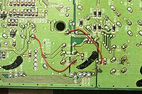
The LM324 was replaced by an LF353 on a carrier board. The LM324 appeared in 1972, so judging from the sound of recordings in those days, a bipolar op-amp from those days probably wasn't up to the task. Reworking the HTR-5230 begins Analog input proved too noisy. Reviewing the available datasheets for the HTR-5230 revealed the TOSLINK input could be extracted from it for use in another amplifier. The dual TOSLINK inputs were multiplexed into a single input by a simple voltage level. The single input went into the 1988 era YM3436 which converted it to I2S. This was configured by simple mode select pins. The I2S went into the 1999 era CS4227 which had the DAC. The I2S was routed through the undocumented YSS908 to process the special effects. It could easily be hotwired to bypass the YSS908. Everything uses 5V at a fairly high current. The CS4227 is configured for SPI. You can see data on the AD1/CDIN line when changing inputs. CDOUT isn't connected. CCLK goes at 100khz & sends 2 bytes when changing inputs. CS is erratic. The initialization merely sets the attenuation registers. Their default is 127 reg value 4 -> 5 5 -> 5 6 -> 13 7 -> 13 8 -> 13 9 -> 23 The analog out after attenuation is 1.8V-2.8V. It goes to a butterworth filter recommended in the datasheet, but requiring +/- 25V. The butterworth filter needs a fairly high current & generates a lot of heat. The final output is -3.3 - 3.3V. The filter GND needs to be raised for it to have a chance. The filter ground fortunately had very few connections. The 1st step was disconnecting the filter ground from the logic ground, which required lifting a few caps & cutting a few traces, but it was perfectly happy. The next step is reversing the direction & removing some caps before raising filter GND to 5V. Also very important to look for any other parts which might explode. |
|
|
Last edited by Jack Crossfire; Aug 27, 2016 at 09:52 PM.
|
|
|
|


