|
|
|
|
Thread OP
|
Discussion
Mobius Mini Support Thread (READ Posts #1-#7 BEFORE posting questions)
Thread Usage Protocol
This thread is hosted by Mobius Mini users, not the camera developer, and is part of a radio controlled model web site in a Forum dedicated to Aerial Photography. As such, the content of this thread is intended to focus on the topic of the Mobius Mini Actioncam and it's operation and capabilities for aerial video purposes, NOT other cameras from the Mobius developer. A basic comparison of those other cameras can be found in this User Thread. That said, the Mobius Mini (a.k.a. Mini) is unique in it's small size, weight, capabilities, and price point, making it ideal for many other uses to capture action video. There will be persons interested in the Mini for purposes other than aerial video directed here for camera support by various vendors, and you are welcome here for the purpose of helping you with the camera's operation. Issues with adapting the camera to uses other than aerial video are considered off topic, and should be discussed in other forums or threads, e.g.:
Video links posted here should relate to the RC aerial video topic area. Examples of off topic videos are:
Finally, this thread is a "self-help" thread! The 6 "info posts" following this one contain much information that can answer many user questions. These info posts will be updated as needed with new information. It is my intent and expectation that thread posters will "do their homework" and access these posts before posting new questions. If you still have questions, the advanced thread search function should be used to help find posts that relate to your issue. This will not only help keep the thread from becoming bloated with redundant questions that have been asked and answered many times, it will also keep the thread more interesting to the target audience. If this is your first time reading this thread, please read the next 6 posts now to familiarize yourself with this thread's structure and resources. These "InfoThreads" will be continually updated with any new information of general interest, so always check here first before asking questions. Thanks in advance for your cooperation! |
|
|
Last edited by Tom Frank; Jun 06, 2021 at 09:11 PM.
Reason: Added link to Other Mobius cameras
|
|
|
|
|
|
|
Thread OP
|
Vendors and Specifications
The Mobius Mini, by the developer of the highly successful original Mobius ActionCam 1 and 2, and the #16HD "808-style" keychain camera, is a unique implementation of highly capable imaging hardware to the more capable 1080p-60 fps level. The features that made the prior cameras from this developer, namely small, light, configurable, great video, and low cost have been retained, with an unmatched diminutive size. Composite video-out latency from the camera is reported to be no more than 60ms in 10809-60fps mode, and 40ms in 720p-120 fps mode (FPV video TX/RX will add to this obviously). The firmware will continue to mature and incorporate all the capabilities of the new hardware, and the developer monitors this thread for user feedback on the camera's functionality.
Verified Vendors [B]You are advised to only buy your Mini from a developer-verified source. Verified vendors not only sell the real Mini camera, accessories, and some replacement parts, they have pledged a commitment to customer satisfaction, both before and after a sale, and are your first contact if any early problems are found and not caused by user abuse, crash damage, etc. If parts are not listed on their sites, use their web site contact link to request what you need. Payment via PayPal is usually available. The developer's China eBay direct seller (eletoponline365) is the official source for the camera's sold by re-sellers, and will usually have the lowest delivered prices as well as common replacement parts not listed in store web pages. They can also relay user feedback to the developer (email eletoponline@gmail.com). The other re-sellers may offer quicker delivery depending on your location. Prices can vary from one vendor to the other and depends on what is included in different accessory packages. The cost from the China direct seller eBay outlets will be nominally about US$69 with free shipping. Direct Seller: China: eletoponline365Re-sellers: China: BangGoodNon-verified sellers may be selling fake imitation cameras at seemingly bargain prices, and you should be wary of buying from them. NOTE: Both users and vendors are expected to abide by this forum and thread vendor communication protocol. Memory Cards Standard Class 10 or UHS-1 microSDHC cards from popular manufacturers should be used for the high data rate recording of this camera. Currently, cards with a capacity up to 200GB can be used. FAT32 formatting will work with ALL cards, and EXFAT is also supported for cards of 64GB or greater capacity. ALL MEMORY CARDS should be formatted using the camera's internal formatting routine for best compatibility!. If you are uncertain about what kind of memory card to buy, order one from the camera vendor when you place your order. Case Design 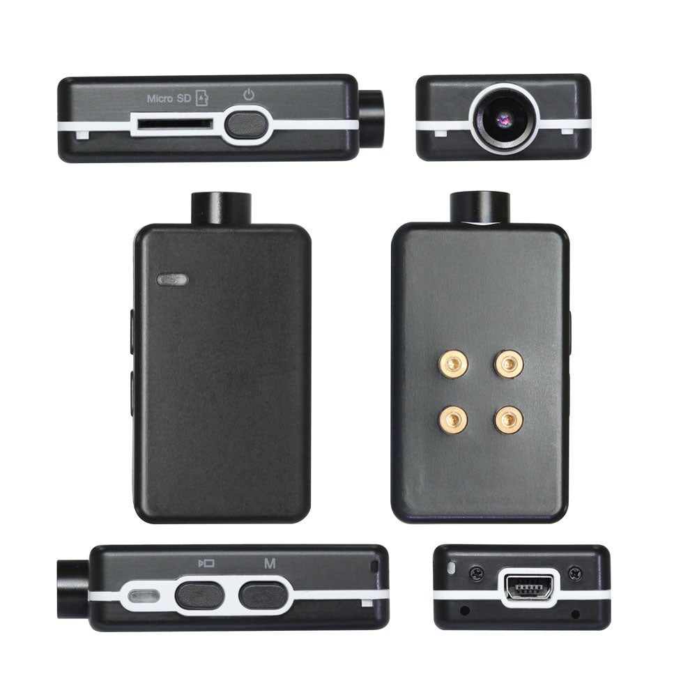 The Mini brings 1080p-60fps video (as well as 720-120 and WVGA-240) in a Mobius form factor with a size much smaller... close to the #16 size.  The weight is nominally only 27 gms. 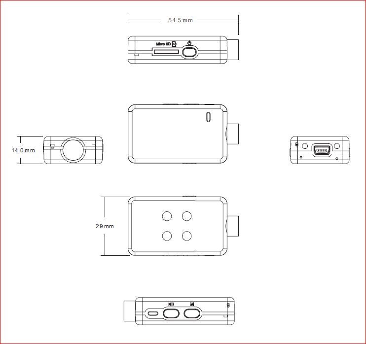 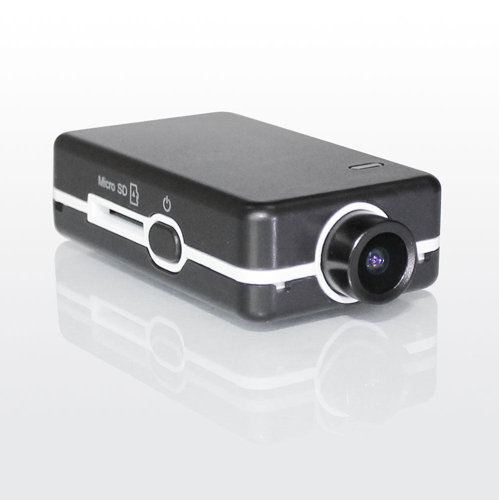    #16 (left), Mini (center), Mobius 2 (right) #16 (left), Mini (center), Mobius 2 (right) #16 (left), Mini (center), Mobius 2 (right) #16 (left), Mini (center), Mobius 2 (right)Embedded into the case bottom is an aluminum heat sink plate with 4 brass screw inserts for attaching a tri-pod mounting piece or other securement.  A clear plastic "light-pipe" insert in the case top is positioned over the 4 circuit board function LEDS to channel the light to the top and side LED view ports. A new V2 case was released in December 2017. Details of the changes are shown in this post. Circuit Board and Battery The circuit board has a reset button and easy disconnects for the battery and CMOS ribbon cable. The charging and external communication port is a standard 10 pin mini-USB socket. An over-voltage protection IC on the USB external power input which will disconnect the external power and protect the camera if the voltage is between 5.6V to 28V. The CMOS imager and DSP chips used in the camera are confidential at the developer's request. The stock 300 mAH battery can power the camera for approximately 30 minutes with full HD recording. 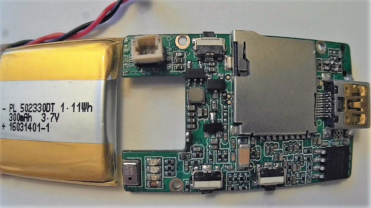 Circuit Board Top Circuit Board Top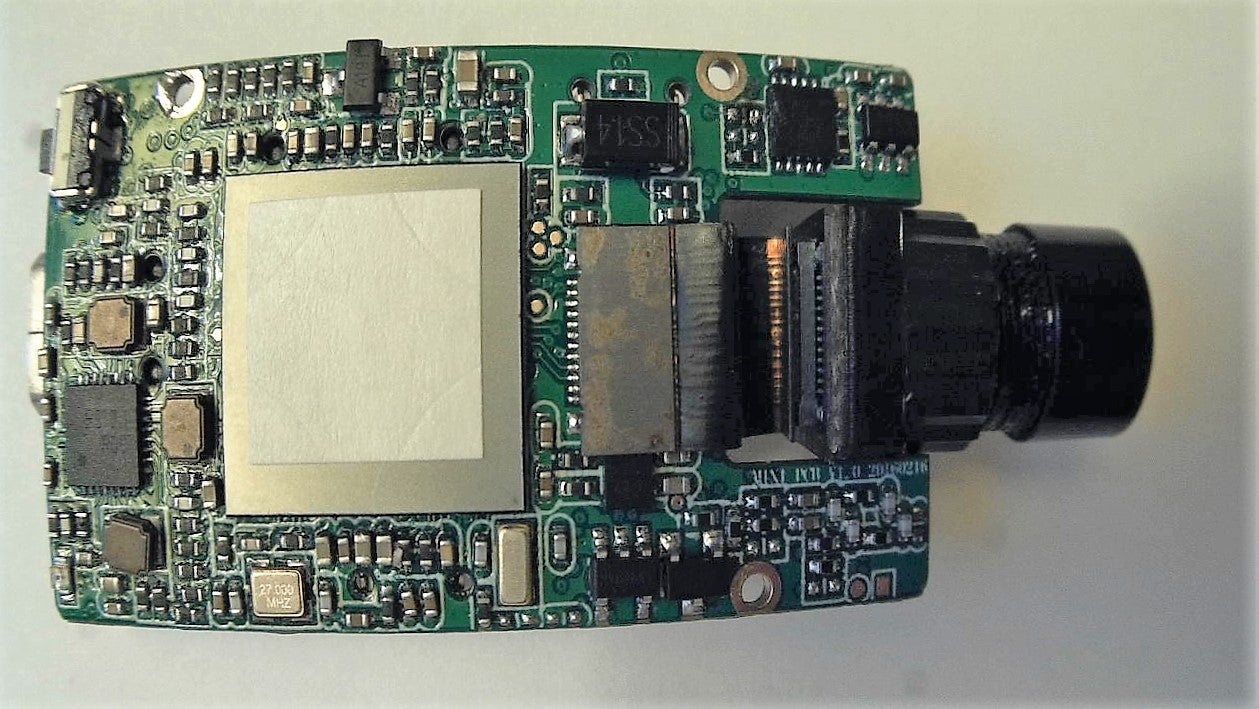 Circuit Board Bottom Circuit Board BottomA new V2 circuit board was released in April 2017 that relocated the ribbon cable socket on the circuit board from the bottom to the top. This greatly facilitates replacing the CMOS/Lens module. Also, the new circuit board has eliminated the problem of a simultaneous pressing of the shutter button and then the power button to trigger the "back door" communication mode that causes the normal button functions to be ignored thereafter, and the camera is locked up until the reset button is pressed. More details here. Lens Module The CMOS imager is on a thin circuit board bonded to the back of the lens module. It's ribbon cable is secured to the circuit board and the CMOS circuit board via a low profile "snap-in" clamping socket on both ends making it possible to replace just the ribbon cable, the CMOS module, or the lens in the module if necessary. The Mini CMOS imager and ribbon cable are NOT compatible any other cameras from this developer. The CMOS has an active pixel array of 2688 x 1520 (16:9 aspect ratio) for full HD video recording.  There are two lenses at release time, Lens A (110 deg.), with narrower FOV similar to the Original Mobius Lens A, and Lens B, with a wider FOV.  Lens A - Smooth barrel and convex front element Lens A - Smooth barrel and convex front element Lens B - grooved barrel and flatter front element Lens B - grooved barrel and flatter front element Lens A - red coating tint in center Lens A - red coating tint in center lens B - green coating tint in center lens B - green coating tint in centerThe lens has an M9 thread and can accept other lenses with matching threads, though 3rd party lenses may or may not have the necessary focal plane diameter or distance from the back of the lens to properly focus and cover the CMOS array to avoid vignetting or cropped corners.  Frame grab from largest video with narrow lens A Frame grab from largest video with narrow lens A Frame grab from largest video with wide lens B Frame grab from largest video with wide lens B Largest still image size with narrow Lens A Largest still image size with narrow Lens A Largest still image size with wide Lens B Largest still image size with wide Lens BA short native sample clip with the pre-release FW can be downloaded or streamed from here. Approximate Weight of Basic Components Stock camera (with battery & card)......... 27 gms. Battery (300 mAH)................................. 6 gms. Circuit board.......................................... 6 gms. Lens module and ribbon cable.................. 4 gms. Case Top............................................... 3 gms. Case Bottom with heat sink and buttons.... 8 gms. Mounting Options The case bottom has 4 M2 screw studs molded into it and anchored in the heat sink inside. These can be used to attach the camera to a flat plate for a mount of your own design. Those studs also accept the stock tri-pod attachment piece (standard 1/4-20 thread) and will mate with a variety of heavy duty mounting accessories. Three of these are a flat surface adhesive pad mount, a bike handlebar mount (accommodates oversize bars), and a lever-actuated suction mount for smooth surfaces such as a car windshield. Each of these specific mounting options use an adjustable articulating ball piece that screws into the base plate, making very minute changes in alignment possible.  The optional helmet mount has both a slightly flexible adhesive pad plus a retaining strap for rugged use. The screw attachment point has only two rotation axes available for aiming the camera.  Another option is a mini-tripod bolt mount for use as a web cam or other use on any level surface.  User Toggled Functions Release FW v0.58 - new functions highlighted in Blue, plus a few bug fixes. Go here for more detail. Basic Functions � Sync Date/Time with PC � Date Display: Date Only, Date and Time, Off � Date Format: YY/MM/DD, MM/DD/YY, DD/MM/YY � Recording Indicator: ON, OFF � Rotate Image: 180 deg., NO, inverted � Artificial Light Frequency: 50 Hz, 60 Hz � TV Video Out Display Mode: NTSC, PAL � Power-Off Standby: Off, 30 sec.,1 min., 3 Min., 5 Min. � Auto-Record with External Power: Off, On . OSD Language: English, Dutch, French, Spanish, Italian Video Functions � Audio Sound: On, Off � Motion detect: On, Off � Image Stabilization: On, Off � Loop recording: On, Off � External Microphone: Enable, Disable � On Screen Display (OSD - in Video Out Mode Only): On, Off to View/Delete recorded images, change config settings, view system info. . Video File Type: MOV, MP4 . Field of View: Wide, Narrow (not available for 1440p, 720p (100 fps or 120 fps), or WVGA) � Two Video Modes - Set Frame Resolution and Frame Rate: 1920x1440@30fps, 1920x1080@60/50/48/30/25/24 fps, 1280x720@ 120/100/60/50 fps, 848x480@240 fps � Video Quality (approx. ave. data rate): Normal (16 Mbps), Fine (32 MBps,) Super Fine (44 Mbps) � Video Clip Length: 1 min., 3 min., 5 min., 10 min., 15 min., Max. (4GB FAT 32 limit) Photo Functions � Photo Frame Size: 2688x1512, 2048x1536, 1600x1200, 1920x1080, 1280x960 � Image Quality (JPEG): Normal, Fine, Super Fine (1.8 MB) � Time-lapse Photos: Off, 3 sec., 5 sec., 10 sec., 30 sec., 1 min. delays � Time-lapse Duration (auto-stop): Unlimited, 5 min., 10 min., 15 min., 20 min. 30 min., 60 min. � Photo Burst (rapid images): Off, 3 photos, 5 photos, 10 photos � Shutter Delay: Off, 2 sec., 10 sec., Photo, Wait (3 sec. delay), photo � View OSD: Off, On Advanced Image Functions Sharpness: Hard, Normal ,Soft Exposure: -2EV to +2EV, in .3EV steps Saturation: +/- 6 steps from Normal White Balance: Auto, Daylight, Cloudy, Tungsten, Fluorescent Lock Mode for Exposure and White Balance: Switch on off at any time with quick power button press Metering: Multi, Center weighted, Center Spot, Upper weighted, Lower weighted ImagesView all Images in thread
|
|
|
Last edited by Tom Frank; Jun 18, 2021 at 12:09 PM.
Reason: minor text cleanup
|


.jpg
Views: 287
Size: 230.2 KB
Description: Board top with CMOS module removed")
.jpg
Views: 274
Size: 262.4 KB
Description: Board bottom with CMOS ribbon cable connected")
.jpg
Views: 286
Size: 299.3 KB
Description: Board bottom with \"snap-in\" cable connector un-plugged")
.jpg
Views: 227
Size: 135.8 KB
Description: Lens A - smooth barrel and convex front element")
.jpg
Views: 229
Size: 106.6 KB
Description: Lens B - grooved barrel and flatter front element")
.jpg
Views: 226
Size: 111.7 KB
Description: Lens A - red coating tint in center")
.jpg
Views: 213
Size: 115.1 KB
Description: Lens B - green coating tint in center")
|
|
|
|
Thread OP
|
Camera Configuration and Firmware
Camera Configuration and Firmware Information
It is strongly recommended that users with Windows PCs always use the mSetup graphical user interface (GUI) program to change camera settings and update firmware. This post has an overview of the Windows mSetup GUI software program authored by Isoprop, as well as the link for downloading it and his detailed Mini User Guide. This thread by Thomas. discusses his Mobius Android App for configuring the Mobius cameras, including the Mini, with a link for downloading the App. New firmware and user settings can be loaded into the camera manually as a last resort (see below), but it requires specific file editing and handling procedures as well as multiple button press sequences on the camera. It is easy for user errors to cause these updates to fail! Also, there are numerous camera settings, some of which conflict with each other if both are toggled on at the same time. The GUI program will not permit these conflicting settings to be set, so do yourself a favor and use the GUI tools if possible. Optional Manual User Configuration Setting Procedure Via Config Text File Editing If a GUI tool is not available for your computer or you would rather just edit the configuration text file manually, it's easy to do, just follow these steps exactly: 1. Download the camera's configuration file to the flash card in the camera (HOLD DOWN MODE BUTTON, THEN ALSO HOLD DOWN POWER BUTTON [the LEDs will flash for several seconds] UNTIL THE YELLOW LED TURNS ON STEADY). 2. Turn the camera on, connect it to your PC, and access the camera root directory when it goes into the "removable disk mode". 3. Open the "SysCfgMini.txt" config text file with a simple (ASCII) text editor (e.g. the familiar "Notepad" text editor for Windows users). The file will look similar to this: Code:
DateTime= 2017/06/25-09:27 ;date time setting,yyyy/mm/dd-hh:mm DateTime_Update=0 ;Confirm to update the Date/Time or not , 0: No, 1: Yes DateStyle=1 ;set date format,0:YYYY/MM/DD, 1:MM/DD/YYYY , 2:DD/MM/YYYY Image_Size=0 ;set image size, 0: 2688x1512, 1: 2048x1536, 2:1600x1200,3:1920x1080,4:1280x960 Image_Quality=0 ;set image Quality, 0: Super Fine 1: Fine 2: Normal Photo_Osd=1 ;set photo preview OSD, 0:Off, 1:On Time_Lapse=0 ;set TimeLapse interval, 0: Off, 1: 3sec, 2: 5sec, 3: 10 sec, 4: 30sec, 5: 1min Time_Lapse_Duration=0 ;set Time Lapse Duration, 0: Unlimited, 1: 5Min, 2: 10Min, 3: 15Min, 4: 20Min, 5: 30Min, 6: 60Min Driver_Mode=0 ;set shutter delay, 0: Off, 1: 2 Seconds, 2: 10 Seconds, 3: 10 Seconds double exposure Photo_Burst=0 ;set Photo Burst, 0:Off , 1: 3 photos, 2: 5 photos, 3: 10 photos Video_Size1=1 ;set Video1 Size and frame rate,0:1920x1440(30fps),1:FHD(60fps),2:FHD(50fps),3:FHD(48fps),4:FHD(30fps),5:FHD(25fps),6:FHD(24fps),7:HD(120fps),8:HD(100fps), 9:HD(60fps),10:HD(50fps),11:848x480(240fps) Video_Size2=7 ;set Video2 Size and frame rate,0:1920x1440(30fps),1:FHD(60fps),2:FHD(50fps),3:FHD(48fps),4:FHD(30fps),5:FHD(25fps),6:FHD(24fps),7:HD(120fps),8:HD(100fps), 9:HD(60fps),10:HD(50fps),11:848x480(240fps) FOV=1 ;set Field of view, 0:Wide FOV, 1:Narrow FOV Video_Quality=0 ;set VideoQuality, 0:Super Fine, 1:Fine, 2:Normal, 3:Extreme(Warning: may have some dropped frames for some memory cards or other issues if set to Extremely High Bitrate.) Media_Format=1 ;set Media Format, 0: MOV, 1: MP4 Sharpness=3 ;set Sharpness, 0:Super Hard, 1:Hard, 2:Normal, 3:Soft, 4:Super Soft Saturation=4 ;set Saturation bias, 0:-6, 1:-5, 2:-4, 3:-3, 4:-2, 5:-1, 6:0, 7:1, 8:2, 9:3, 10:4, 11:5, 12:6 AE_Metering=1 ;set AEMetering method, 0: Center area, 1: Multi spot, 2: Center spot, 3: Top, 4: Bottom Exposure=6 ;set Exposure bias, 0:-2.0, 1:-1.66, 2:-1.33, 3:-1.0, 4:-0.66, 5:-0.33, 6:0, 7:0.33, 8:0.66, 9:1.0, 10:1.33, 11:1.66, 12:2.0 Movie_Voice=2 ;set recording voice, 0: Off, 1: Low, 2:Normal, 3:High Ext_Mic=0 ;set extern micphone, 0: Off, 1: On Stabilizer=0 ;set stabilizer, 0: off, 1: on Loop_Record=0 ;set loop record, 0: Off, 1: On Recording_LED=1 ;set recording LED, 0: Off, 1: On Clip_Length=5 ;set clip length, 0: 1 Min, 1: 3 Min, 2: 5 Min, 3: 10 Min, 4:15 Min, 5: Max to 4G Invert_Mode=0 ;set sensor Flip, 0: Off, 1: On White_Balance=0 ;set white balance mode, 0: AWB, 1: Daylight, 2: Cloudy, 3: Tungsten, 4:Fluor AE/AWB_Lock=3 ;set AE/AWB lock(quick press power button to set locks), 0: AE/AWB lock off, 1: Both AE/AWB, 2: Only AE, 3: Only AWB Video_Osd=1 ;set video preview OSD, 0: Off, 1: On Motion_Detect=0 ;set Motion Detect, 0: Off, 1: On MD_Sensitivity=0 ;set Motion Detect Sensitivity, 0:High, 1:Normal, 2:Low MD_Timeout=2 ;set Motion Detect Record time, 0:5s, 1:15s, 2:30s, 3:60s, 4:3Minutes, 5:5Minutes pwn_auto_rec=0 ;set Auto Record with external power, 0: Off, 1: On TV_Full_Screen=0 ;set Full Screen On/Off, 0: Off, 1: On Sleep_Time=1 ;set auto-shutdown delay, 0: Off, 1: 30 sec, 2: 1 Min, 3:3 Min, 4: 5Min Language=0 ;set Language, 0: English, 1: Deutsch, 2: Fran?ais, 3: Espa?ol, 4: Italiano, 5: Russian Light_Freq=1 ;set Light Frequency, 0: 50Hz, 1: 60Hz Date_Stamp=2 ;set DateStamp, 0: Off, 1: Date, 2: Date and Time TV_Mode=0 ;set TVMode, 0: NTSC, 1: PAL FIRMWARE: V0.92 5. Save the file back to the memory card. 6. Load the config file back into the camera with the same button press sequence used to extract it, and you're done! The config file will be deleted from your memory card automatically after it loads back into the camera. If you want to keep it on the card for re-use at a later time, set the attribute flag on the file to "read only" with your computer when you are finished editing it. This can be handy for making frequently used config changes in the field without a computer or smart phone App, or FPV/monitor setup to toggle the settings via the camera's OSD display method. Alternate Manual User Configuration Setting Procedure Via Camera's Video Out OSD The Mini has an On Screen Display (OSD) mode that can display/change its configuration settings via the camera buttons. To use this you must have a TV, FPV system, or other monitor that can display an analog NTSC or PAL composite video signal. This method is a bit unwieldy navigating through the various menus to toggle settings, but there are times when this might be the only method available. You MUST have the Mini USB Video Out cable to feed the OSD video to your display hardware. More details on this are in Isoprop's User Guide linked above. Firmware Firmware updates will contain bug fixes, new or improved features, or both. You are advised to always update the firmware if you want your Mini to give you all it can. You are strongly advise to ALWAYS use the GUI tool for all camera firmware changes (see above). The GUI will determine if your camera firmware is out of date, download the latest firmware if you agree, and install it for you, taking all the potential for user error out of it. The firmware development and refinement is a continuing process, and the most recent OFFICIALLY RELEASED versions will be kept attached to this post as downloadable zip files. Any problems found with the Released Firmware should be reported to me via PM. The most up-to-date firmware is available for manual download at the bottom of this page. Optional Manual Firmware Update Procedure The following procedure is for manually updating your camera firmware. It is not necessary to do this if you can use the Windows GUI configuration tool (see above). It will determine if your camera firmware is out of date, download the latest firmware if you agree, and install it for you, taking all the potential for user error out of it. You are strongly advise to ALWAYS use the GUI tools for all camera firmware changes. ALERT:
Copy the actual firmware file (FWTPMN.BRN) from it's identifying folder into the camera's flash card root directory (the one that opens when the camera connects as a removable drive). This can be done with the card in the camera connected to the computer as a Removable Drive, or externally in a card reader. But do NOT rename the file. If you do, the camera will not install it! 2. Disconnect the camera and turn it off. 3. Insert the flash card containing the new firmware file into the camera (if not already in the camera). 4. Press the Power button until the camera turns on, then RELEASE THE POWER BUTTON AS SOON AS LED FLASHING BEGINS! If you keep pressing it longer, you may turn off the camera before the update process is done. DO NOT PRESS ANY BUTTONS WHILE THE INSTALLATION IS IN PROGRESS . 5. To confirm the firmware is being loaded into the camera, the LEDs will continue to blink during the upload process, which takes about 40 sec. 6. When the FW installation is complete, the BLUE LED will turn off for about 40 sec. and the YELLOW LED will then turn on solid, indicating the FW file is has been automatically deleted from the memory card. 7. You're done! The camera will be in the normal start-up standby mode ready for use. Firmware Download Site |
|
|
Last edited by Tom Frank; Sep 21, 2021 at 10:06 PM.
Reason: minor corrections.
|
|
|
|
|
Thread OP
|
Camera Care and Maintenance
Camera Mounting
The tiny case of the Mobius can accumulate a lot of internal heat when it's recording, with simultaneous battery charging and Video Out operation adding to the heat generated. The case has an internal heat sink plate in the bottom with just 4 brass screw studs penetrating through the case bottom to attach a standard tripod mounting piece. It is important to NEVER MOUNT THE CAMERA WITH THE CASE BOTTOM HEAT SINK AREA FLUSH ON ANOTHER SURFACE! Doing so will restrict the heat release from inside the camera and can cause overheating of the electronics, and may result in thermal over-load shutdown or permanent damage to the camera. If mounting the camera case flat on a mating surface is necessary, always flip the case upside down leaving the bottom heat sink area exposed to ambient air, and invert the recorded image (if necessary) using the camera's configuration setting. This temperature issue is even more critical when the camera is mounted inside a car for use as a driving recorder. The internal battery should be removed from the camera in this case, with only external USB power used for powering the camera. The battery should be replaced with the capacitor accessory module to give enough power to save a recording if external power is interrupted, and to keep the camera internal clock running when external power is not provided for a couple of days. Battery Replacement A. For new V2 case with the ventilation slots on the sides 1. Remove 2 screws on the front of the case, and gently lift the top and separate the two case halves. 2. To remove the battery, do NOT pull on the wires to unplug it! I use the plastic tool mentioned above to wedge and twist between the plug and socket "lips" to lift the plug out of the socket without putting any stress on the wires or circuit board. 3. To finish, plug in the battery and align it and it's wires so there is no interference when the case top is re-installed. 4. Engage the rear locking tabs on the rear of the case into their retaining slot, then lightly press the front of the case into position and re-install the two tiny screws to secure it to the halves together. Don't over tighten the screws. 5. DONE! Test the camera to confirm it is working. B. For the original case with the white plastic mid-piece: 1. Remove 2 screws on case rear and gentle lift the rear end of the case until it just barely clears the case bottom. 2. Gently nudge the case top forward with your thumbs while holding the case front with your fingers so it cannot suddenly release and hit the lens, jerking and stressing the ribbon cable. Alternatively, I use the cap from a ball point pen as a lever nudge the case top forward so it can't move very far when the lugs that hold the two case halves together on the front disengage. When they release, remove the case top. 3. To remove the battery, do NOT pull on the wires to unplug it! I use the plastic tool mentioned above to wedge and twist between the plug and socket "lips" to lift the plug out of the socket without putting any stress on the wires or circuit board. 4. To finish, plug in the battery and align it and it's wires so there is no interference when the case top is re-installed. 5. Place the front of the case top into position and press it aft lightly to re-engage the small lugs on the front of the case halves, allowing the rear of the case top to clear the case bottom. Lightly press the rear of the case top into position and re-install the two tiny screws to secure it to the case bottom. 6. DONE! Test the camera to confirm it is working. Lens Module Replacement A. For new V2 case with the ventilation slots on the sides The new case eliminates the difficulty with the prior white plastic mid-piece case design. 1. Open the case and remove the battery as described in steps 1 and 2 above for the V2 case. 2. Gently lever off the ribbon cable connector out of it's snap-in socket on the circuit board with a small wood or plastic tool. Do not pull on the ribbon cable to remove it. 3. Next gently lever out the lens module from its seat in the case. There is double-backed tape holding the lens barrel in place, so go slow and don't apply a lot of force. 4. When replacing the module, make sure the ribbon cable connector if fully snapped into position. The battery will hold it securely in place when it's reinstalled. 5. Replace the battery and rejoin the case halves per steps 3, 4, and 5 above for the V2 case. B. For the original case with white plastic mid-piece and circuit board released in April 2017 with ribbon cable attached to the top of the board of the board The new board makes it much easier to replace the lens module, but it is still necessary to remove the circuit board to extract the lens module through the white plastic case ring around the lens barrel. 1. Begin by first un-snapping the ribbon cable plugs on each end from their sockets. This can be done by placing a tool (preferably a plastic one like the ball pen cap I use) under the corner of the ribbon cable connector in the socket and GENTLY ROCKING it side to side to disengage the plug from the board socket. 2. Then follow steps 1 through 4 below to remove the lens module (ignore the ribbon cable cautions) and replace the lens module. 3. If you received the camera with the new circuit board installed, the buttons should be lightly secured with tape to hold them in place when the board is removed, making it easier to slide in the lens module and reassemble the camera. If the new circuit board is being retrofitted in an earlier camera case, you may need to adhere to the case button positioning suggestions in step 7 and 8, below when re-assembling the camera. Also, the lens module will need to be inverted to accommodate the new plug orientation using the existing ribbon cable. Be SURE to plug in the ribbon cable with the end labelled "Main" into the circuit board, NOT the module. The cable will not work if reversed and may damage the components! The old ribbon cable may need re-bending to facilitate the new positioning, and that might crack a trace in the cable ruining it. It is advisable to order a new ribbon cable if the new board is being retrofitted in an old case in the even the cable is damaged. C. For the original case with white plastic mid-piece and Circuit Board with ribbon cable attached to the underside of the board The Mini disassembly is not an easy task, but can be done with care if you do not rush it to minimize the inherent risk of damaging the CMOS ribbon cable or circuit board. Here are the key steps: 1. First, open the case and remove the battery per steps 1 to 3 above, then remove the three tiny screws that secure the circuit board to the case bottom. 2. Now comes the hard part! The USB plug extends through a hole in the case bottom, so the rear cannot lift out vertically. You must lift the front of the circuit board until it just barely clears the bottom of the case so the board can slide forward just far enough to allow the rear of the board to be lifted vertically out of the case bottom. There is likely a piece of heat transfer tape between the DSP chip and the heat sink on the underside of the board that you cannot see. It has sticky backing and will likely hold the board to the heat sink making it difficult to lift the front of the board. The circuit board also has a snug fit around the sides at the buttons, so to free the board the very front edge of the board needs to be lifted. To do that, you can wedge a tiny jewelers flat head screwdriver between the circuit board edge and the case at the buttons, and twist it gently to allow the button "nubs" to clear the switch pins and lift the board upward. Start at the power button side since it's easier with just one button. The board can then lift up and tilt slightly making it easier for the board to clear the two button on the opposite side. Alternatively, you could resort to using a paper clip with a very short 90 deg. bend created on the free end (I hesitate to recommend this!). Insert the "hook" end of the paper clip in the gap at the front of the board, rotated it 90 deg. so the hook could lift the board, and GENTLY, working each side at a time, gradually freed the board so the front could be lifted vertically to clear the case bottom. CAUTION: This puts bending stress on the circuit board which could crack a trace or solder point somewhere. Here is an alternative method for freeing the circuit board from the tape. 3. With the front of the board slightly above the case bottom slide it forward just enough to allow the USB plug on the rear to disengage from the hole in the case bottom, and lift the rear of the board free. CAUTION: To do this, the rear of the lens module must also be lifted at the same time since it prevents the board from moving forward far enough. This will extend the folded ribbon cable in the process, so GO SLOW, BE CAREFUL not to over-do it. You will NOT be able to remove the lens module from the case at this point since the lens barrel passes through a round hole in the case bottom piece! 4. With the rear of the circuit board finally lifted free, slide if aft slightly and SLOWLY and CAREFULLY work the lens back through the circular hole in the case bottom piece. DO NOT over extend the ribbon cable or pull on it... you could damage it! The lens WILL fit through the hole in the case, but there is very minimal clearance and it can jam if not positioned in line with the case bottom. DO NOT FORCE IT and DO NOT try to pull it through with the ribbon cable or you could damage the cable. 5. With the lens module free from the case bottom, turn over the circuit board and the lens module as a single unit, being careful not to overly twist the ribbon cable. You will see the ribbon cable is attached to the circuit board with a "snap-in" connector. It can be freed by placing a tool (preferably a plastic one like the ball pen cap I use) under the corner of the ribbon cable connector in the socket and GENTLY ROCKING it side to side to disengage the plug from the board socket. 6. SUCCESS (I hope)! Re-assembly is basically reversing the dis-assembly steps, but before starting you probably noticed the buttons that reside in the bottom portion of the case easily fall out of their slots. This requires preparation before you start to re-assemble the camera. 7. First, make sure the buttons are in their proper slots in the case bottom with the power button properly aligned! The power button is slightly smaller than the other two, and there is a small protrusion on the inside that contacts the plunger on the power switch. That protrusion is NOT in the center of the button, and needs to be inserted with it closer to the front of the case in order to line up with switch plunger.  The other two buttons are identical and symmetrical, and can be inserted into their openings in the case bottom without any special orientation of the plunger protrusion. 8. Secure the buttons temporarily in the case bottom with tape over them on the outside of the case. The buttons fit very close to the switch plungers, and need to be held in a fully retracted position by the tape so they do not fall out as the lens module and circuit board are re-inserted into the case bottom. 9. Carefully align and lightly press the lens module ribbon cable connector into the circuit board socket. After making sure it is fully seated, turn the lens module and circuit board over as a unit making sure not to over-twist the ribbon cable. 10. Align the lens barrel with the circular hole in the case bottom, and gently work it's way through the hole. Do not over-extend the ribbon cable in the process. 11. Gently lift the lens module so the circuit board can move forward just far enough for the USB socket on the aft end to clear the back of the case and drop into alignment with its hole in the case bottom. Gently slide the circuit board aft so the lens module can be dropped back down into position. Again, do not over-extend the ribbon cable. 12. Reseat the circuit board into the case bottom. If the circuit board does not slip easily into position, do NOT press hard to force it into place. The buttons may not be fully retracted to clear the switch plungers and you could damage them. If this is the case, lift the board slightly and slip a piece of paper between the button(s) and the switch plungers. The paper will keep the buttons and plungers separated as the circuit board is lightly pressed into position. 13. Once the circuit board is fully in place in the case bottom, remove the paper if it was used, remove the tape over the buttons, and secure the circuit board to the case bottom with the three small screws. 14. Finish the job by following steps 4 to 6 in the above Battery Replacement procedure. |
|
|
Last edited by Tom Frank; Jun 18, 2021 at 11:30 AM.
Reason: Added battery and lens module replacement instructions for the new V2 Mini case.
|
|
|
|
|
Thread OP
|
FAQS and Other Information
FAQS
|
|
|
Last edited by Tom Frank; Sep 15, 2017 at 12:00 PM.
|
|
|
|
|
|
Mobius Mini Configuration Software and User Guide
This is the original Mobius GUI which was created in co-operation with the developer and Tom.
The program supports all Mobius cameras (Mobius, Mobius2, Mobius Mini) as well as the #16, which was also developed by the Mobius team. Click HERE to download the GUI and/or User Guide. The program is a native Windows application specifically written for the Windows operating system (XP and above) and does not require any 3rd party runtime system, for example Java or .NET, to be installed. The simple and extremely user-friendly program is fully plug-and-play and includes an integrated User Manual. The software will also identify all unknown USB cameras and devices with a capacity of 200GB or less. So, if the GUI doesn't recognize your camera, you don't have a #16 or a camera from the Mobius family! If you don't yet have the camera you may want to take a short peek at the integrated help, available by clicking the 'Help' button. Remember you can resize the dialog by dragging the gripper at the bottom right corner if you prefer a smaller image. The dialog fonts will automatically be resized to fit. The latest GUI software configuration tool together with the latest instruction manual (User Guide) may be downloaded by clicking on the link above or on one of the images below. I strongly recommend you enable automatic program and firmware updates which will allow you to always benefit from the latest available tools. This is specially worthwhile during the first few weeks after the initial release. Here are some screenshots of the GUI (Graphical User Interface) 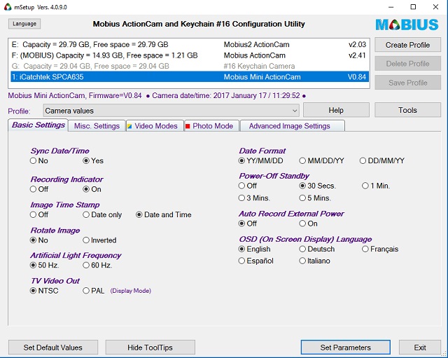 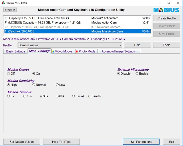 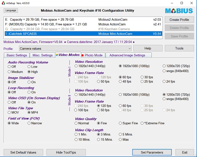 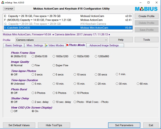 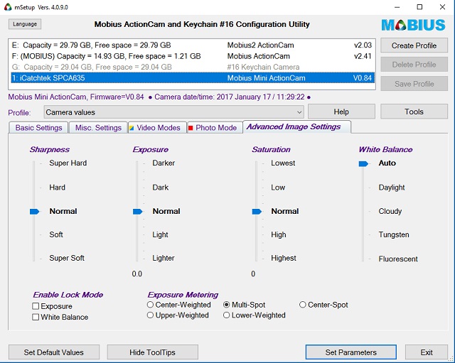 ... there's always an online user guide (manual) at your fingertips 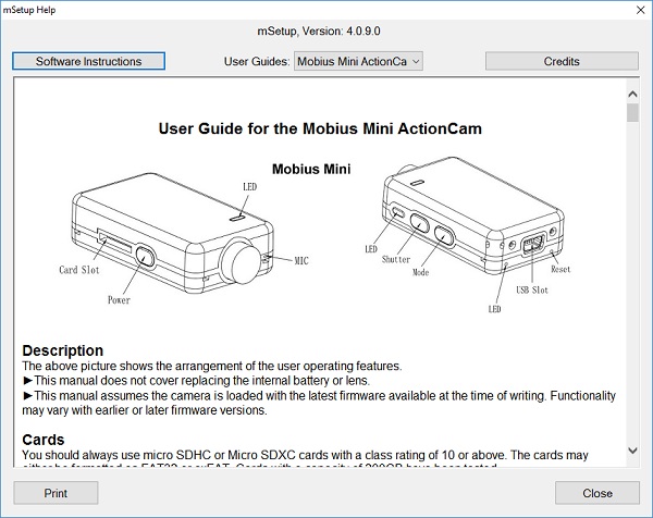 ... you can set your own parameters and download new versions 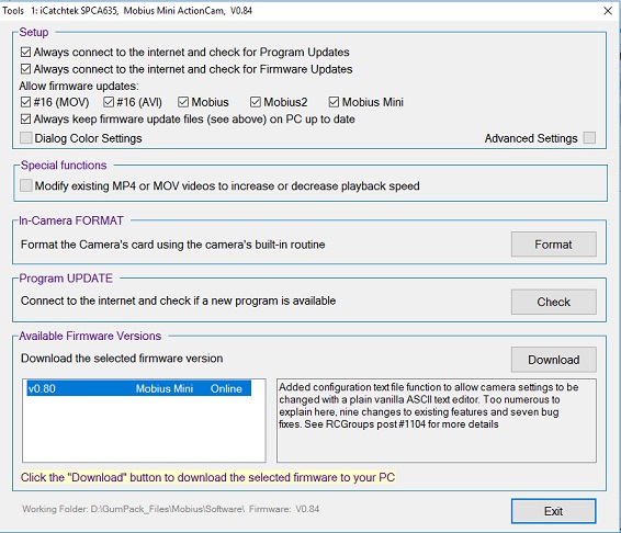 ...and of course you can set your own colors for the program 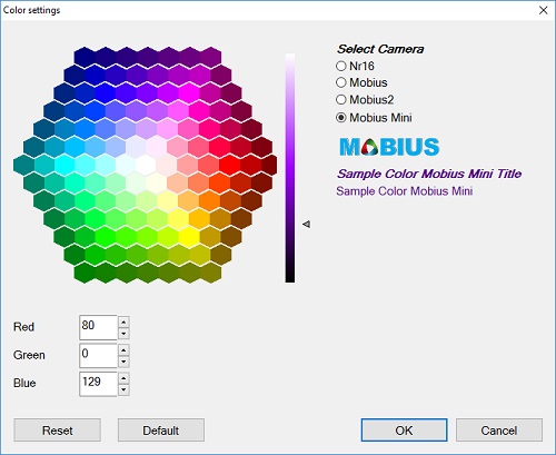 ... There's also a function where you can increase or decrease the playback speed of any .mov or .mp4 media files 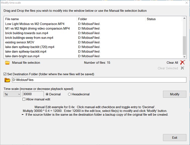 ...and lots of useful information too 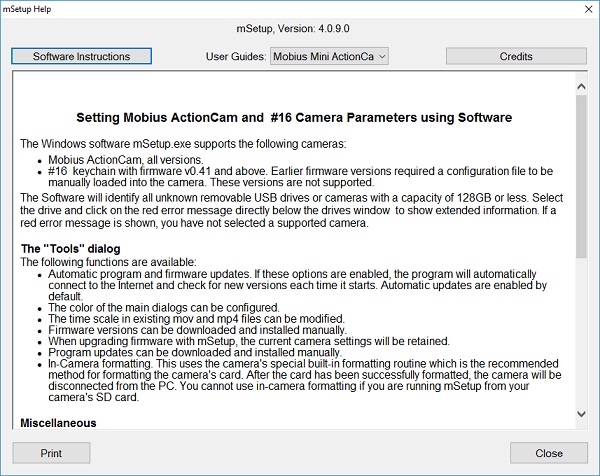 To date, mSetup has been translated into 13 different languages: Traditional Chinese, Czech, Dutch, French, German, Hindi, Hungarian, Japanese, Polish, Portuguese, Russian, Spanish and Turkish. Many, many thanks to all translators for your hard work! Here's an example: 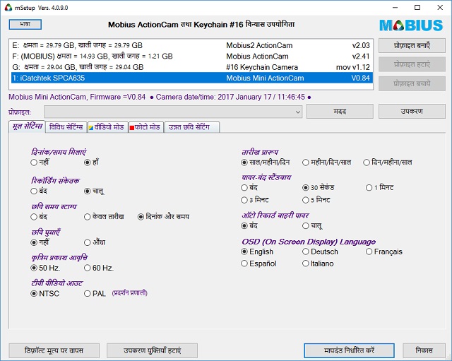 mSetup is guaranteed 100% Clean, which means it does not contain any form of malware, including but not limited to: spyware, viruses, trojans and backdoors. Click the image below for more information. 
|
|
|
Last edited by Isoprop; Apr 10, 2019 at 08:40 AM.
|
|
|
|
|
|
Cables and more
The Mobius Mini uses the same cable as the Mobius Maxi. It is similar to the Mobius2 (M2), except for the external Microphone.
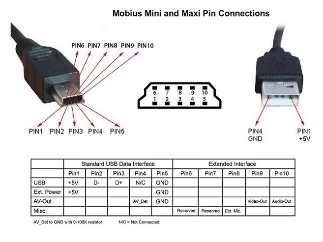 External Microphone (Pin #8) nianeko1, from RC Groups, has created a DIY video showing how to use an external microphone with the Mobius Mini and Maxi. He uses a different pin numbering scheme to the one shown above, so beware! Battery Plug The Mobius Mini uses a Micro JST SH 1.0mm 2-Pin plug for the battery. It is the same as the plug used for the Mobius Maxi. |
|
|
Last edited by Isoprop; Apr 10, 2019 at 11:43 AM.
Reason: Added external Mic.
|
|
|
|
|
|
Android application Mobius ActionCam now fully supports also Mobius Mini! More info in this thread.
|
|
|
Last edited by Thomas.; Jan 29, 2017 at 07:01 PM.
|
|
|
|
|
Thread OP
|
OK, this new thread is replacing the Pre-release Mobius Mini thread I used to give advanced information that was in the final stages before the camera was released for sale. That thread is now closed, but if interested in the discussion there, here is the link to it.
I ask everyone to PLEASE keep your posts on topic, and do not treat this thread like an anything goes blog of comments such as you find in online social networks like Facebook, Twitter, etc. This kind of banter adds nothing of general interest to the readers who come here looking for useful information or help related to the Mini camera. Thanks in advance for your cooperation. 
|
|
|
|
")
|
|
||
|
|
wish I had known it was available from us seller for just a few bucks more!
Quote:
-Cause i would have gladly made this post in that thread....instead of cluttering this one up, but it was closed. 
|
|
|
|
|||
|
|
Ordered one yesterday, will be interested to see how this turns out.
I uploaded the sample clip to youtube, as I find it more interesting to see the result there. Hope Tom does not mind, otherwise I'm happy to delete it.
|
||
|
|
|||
|
|
|
|
|
With the dimensions already posted, the comparison in size with the mobius 2 is clear enough, but I'm more interested in how the features of the mini compare with the M2. Any chance we can have a side by side comparison of specs and performance posted in the opening posts of this thread?
|
|
|
|
|
|
|
|
|
So glad to see this camera - can't wait to get it on my 130 quad! Working on a project for this and M2. Hope to post more info here soon.
Isoprop, your software for PC looks great! (I have used an older version on my original Mobius.) I just wish there was something as nice for Mac (for these newer cameras). Thanks for posting the screenshots. |
|
|
Last edited by scottyo; Aug 24, 2016 at 04:27 AM.
|

