|
|
|
|
|
Discussion
Solidworks/Cad Playground
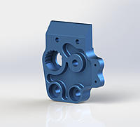
I've been drawing up a lot of bike parts lately and this one was pretty interesting to do. GPV-1 Left Chassis Block
If anyone else wants to show a nice render of something they've done, feel free to post it here. |
|
|
Last edited by katana2665; Sep 03, 2017 at 08:20 AM.
|
|
|
|
|
|
|
|
And the right side...
|
|
|
Last edited by katana2665; Sep 03, 2017 at 08:20 AM.
|
|
|
|
|
|
A few more from the past year or so. 5th scale bits.
|
|
|
Last edited by katana2665; Sep 03, 2017 at 08:24 AM.
|
|
|
|
|
|
Nice! Looks familiar! Lol
Are the left and right blocks mirrored or clocked to the same cam position? |
|
|
|
|
|
|
|
|
They are partially mirrored. The cam positions are mirrored. Other basic features are mirrored and then the more specific details applied to the mirrored piece.
180 degrees with 1.5mm Dia. indents...I guessed on this though....with part in hand. It must have been a pain to figure this part out originally huh? |
|
|
Last edited by katana2665; Jan 18, 2015 at 12:19 AM.
|
|
|
|
|
|
Yep, each indent is about 0.7mm change in chain tension if I recall. The other one that adjusts the swingarm position and chain tension was more challenging because of the range of motion and interaction.
Cool stuff, keep going and make a bike! |
|
|
|
|
|
|
|
|
You mind some dumb questions? How do you start off replicating a part that's already made? Do you use graph paper and measure out the holes or trace the part? Second leading question is in determining hole positions and how you do that? Do you measure distance of outer edge of a hole, then measure diameter to get hole size and position?
Ive always wanted to tinker with ideas but never have the $ to just throw down on a program just to have fun with. |
|
|
|
|
|
|
|
|
Best thing I can tell you is to start with a simple part, like a flanged bearing. Basically if I have the part in hand I use a very accurate steel metric ruler and a dial caliper. In addition I have supporting documentation in the form of manuals. The manuals can give you a lot of information as to what typical bearing and screw sizes are. The rest of the vast reference comes from photographs.
I have several bike projects going on at the moment in Solidworks. The key is to model each part from simplest to most difficult until you get enough knowledge to tackle things another way. In my case though i started building model kits 45 years ago, I have been a machinist, a product designer and a professional modelmaker over the years. For the past 15 years I have worked extensively with 3D animation/modeling programs, so alot of this comes second nature. Heck even modeling a button head hex screw with threads in 3mm can teach you much....not that you would need one so detailed in a design drawing. Also try Google Sketchup. It's Free and can get some basic stuff down just for the sake of ideas. More to come. |
|
|
|
|
|
||
|
|
Quote:
Hole positions and such are as you stated for best guess. There are production tolerances that may make dimensions less than obvious and not round numbers. So you do your best to interprate the design intent. +1 on Google Sketch Up Ive tried it but have not spent much time with it. |
|
|
|
||
|
|
|
|
|
I am working with Solidworks which is cad based and so the parts are accurately dropped into something like Makerbot or sent to a CNC machinist with predictable results.
I initially used 3DS Max to work out designs, but when doing the conversion (.stl) file, the scale was way off. Also the interpretation of a 3D modeling program built for animation, while it works fine for organic things, isn't really the tool of choice for mechanical objects that need precision. Which tool? Anything that is cad based. I tried Autocad early on, but the learning curve was more steep than Solidworks, which made more sense. Everything I learned was found on Youtube, tutorials online and documentation. |
|
|
|
|
|
|
|
|
I've been using Alibre (purchased by 3D Systems and now called Geomagic) for years. It's very similar to Solidworks, but quite a bit cheaper.
I've just now started playing with Autodesk's Fusion 360. The user interface is much different than I'm used to, but it has integrated 2.5 and 3D CAM - instead of having to export your files out to an .igs and import into a separate CAM application. It is cloud based so you have to be connected to the internet to use it (there is a work offline setting, but I haven't tried it), but it is free for non-commercial (and start-up) use. I know you don't get the 3D CAM functions in the free version - maybe the 2.5D not sure. But it can't hurt to give it a shot for free. Dave |
|
|
|
|
|
|
|
|
We used Solidworks as well as Geartrax.
|
|
|
|
|
|
||
|
|
Quote:
|
|
|
|
||
|
|
|
|
|
Swingarm block with color adjustment. Inspired by Edi's Jabber one.
|
|
|
Last edited by katana2665; Sep 03, 2017 at 08:34 AM.
|


