|
|
|
|
|
Strange, thought I posted last night but it's not here, must have missed pressing the 'submit' button!
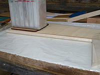
Bit the bullet and drilled the wing mount bolt holes. Used a length of string to check for equal distance between the tail and wing tips. The supplied 'T' nuts are quite a bit longer than the ply mounting plate and the spikes would have popped through so I doubled the thickness by making a pair of Liteply penny washers. GB |
|
|
|
|
|
|
|
|
|
|
Rudder
Another full day ending with a head scratching problem!
I will devote this post to the rudder build as I'm getting a bit mixed up myself!!  The rudder is a foam veneer core with balsa strip surround and a balsa balance horn. Nothing difficult about making it, I had read about people experiencing warped rudders, why it should warp I don't know. It did want to curl a little bit on the board, just held it down with weights. The strip stock was undersize and could not be used for the leading edge, scrap box to the rescue. The trailing edge is quite thick, I think it is supposed to be that way! GB ImagesView all Images in thread
|
|
|
|
|
|
|
|
|
Tailplane and slot cutting
Gathered together all the parts for the tailplane and elevators, quite a chunky piece of kit but a reviewer did manage to break one!!
A template is provided with the instructions to mark the tailplane mounting slot, in addition a reference point on the fuselage is given to check with a straight edge. I found the template disagreed very slightly with the straight edge method so I used a mixture of both!! Slot cutting went well and early indications are that I got it right, tailplane is nice and square to the fuselage. Made a couple of holes for rudder pull-pull leadouts (provided on the template) and had a think about how I'm going to drive the elevators. My old Xtra Wot used a single rod driving a natty 'Y' splitter, looked at using it but it weighs too much and is overcomplicated. Dinner time then on to my problem! GB ImagesView all Images in thread
|
|
|
|
|
|
|
|
|
With the rudder complete I could look at dry fitting the fin.
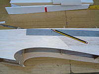
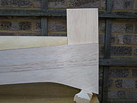
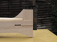
A problem that I can't work out at the moment is the fin fillet leading edge does not line up with the fin or the rudder!! The rudder and fin seem to be the right length, will have another look at it and see if I've done something stupid. All good fun! GB Ed's note:On final assembly the fin ended up slightly out of line with the fillet leading edge off of the centreline, not noticed until after the epoxy had set! Looks like I accurately marked the centreline for the slot cutting but possibly not the edges of the slot. Would extend these lines forward and also add pencil lines to the foam turtledeck to check for alignment. |
|
|
Last edited by Gary Binnie; Mar 16, 2015 at 02:32 AM.
Reason: Add a note
|
|
|
|
|
|
Well, I've checked and double checked and really can't see that I've made a mistake.
The fin and fillet look pretty much as they should be according to the small scale drawings on the parts list. There is no plan to check against, Chris's kits pretty much don't have plans as they are not needed (except in this case!). To fix the problem I could just insert a strip at the rear end (noting that the grain direction is diagonal). I will give Chris a ring as I'm still concerned that I've done something silly or misread the instructions. GB |
|
|
|
|
|
|
|
|
I don't understand what you're doing in post #19: In the fourth picture you've inserted the stern post into the slot, and its rear edge lines up with the rear edge of the fuselage; in the fifth picture things seem to be leaning back, and you seem to have added a triangular fillet along the rear edge to make it a straight line again.
If I've interpreted the pictures correctly, that's why you've then got a mismatch in the line of the triangular piece at the front (pictures 6 and 7) -- because the stern post is leaning backwards and, thus, revealing more of its front edge than it should. If the stern post were vertical I think it would match the triangular piece for height, though you may have to sand the rear edge of the triangular piece to make it the correct less-than-90-degree angle for an exact fit. |
|
|
|
|
|
|
|
|
Mmmm...maybe a bad camera angle in the earlier photos. Is there any chance you could measure your fin fillet, length and height? Appreciate that you probably can't see the join now!
Took some more pictures that are straight on and a few of the thing rigged. Rang Chris but he's away on holiday until next week. Going to have a day off building and go flying instead. GB |
|
|
|
|
|
|
|
|
The overall layout is dictated by the height of the rudder, which shouldn't extend below the fuselage. So personally I wouldn't worry about it -- from the latest pictures it looks like when you create clearance between the top of the stern post and the underside of the front-facing part of the rudder, the bottom of the rudder will be flush, as it should be. If so, I'd then add a packer to the bottom of the triangular piece to make it line up nicely with the leading edge.
I'll give you the measurements of mine in a couple of hours. |
|
|
|
|
|
|
|
|
Here's pictures of the tail of mine, in case it helps. The measurements indicated by the red lines on the second photo are 195mm from the front of the triangular piece where it joins the deck, to the rear of the rudder post (I can't see the join
 ); and 81mm from curved deck up to the top of the vertical stabiliser. ); and 81mm from curved deck up to the top of the vertical stabiliser. Remember, mine is an older model than yours, so dimensions and/or details might have changed. By the way, while I think about it, I haven't experienced any problem with the forward-projecting tips of the elevator digging into the ground. They're actually there to help in aerodynamically balancing the surface, so that it takes less power to move it. Installing the tips on the horizontal stabiliser instead of the elevator, as I think you mentioned in an earlier post, might not be a good move. |
|
|
|
|
|
|
|
|
Very useful, thanks.
The length is about the same and the height of the fillet is about 81 mm (same as yours) but the fin is about 90 mm, very strange. Think I'll bolt the tail skid on to make sure the bottom of the rudder is in the right place. There is an update sheet with the instructions (2002) with three revisions on it. First one is a hardwood strip along the top centre of the forward fuselage under the decking, second is the elevator tip mod and the last is carbon reinforcement for the tailplane. No reason is actually given for the elevator mod, I might have read about it in Neil Tidey's magazine review. I've not glued anything yet so I'm free to choose. Just noticed that my first Xtra Wot had full-span elevators, another variation! |
|
|
|
|
|
|
|
|
The hardwood strip is just a length of 1/8 x 3/8 spruce strip fitted vertically, suppose it ties the formers together and gives a little bit more gluing area.
I don't know the 'ins and outs' of the tailplane saga but as I understand it a magazine reviewer managed to snap a tailplane in the air. The wording is 'if you intend to over power your Xtra Wot or fly it in an 'aggressive' manner we recommend strengthening the tailplane'. The carbon (not supplied) is two 4.5 mm rods, 200 mm long let in to the leading edge of the main tailplane panel, I will do this mod so you can see where it goes. Who knows how or why it failed, if the model was in a screaming power dive and full elevator applied that might do it, wouldn't be good for the wings either!! |
|
|
|
|
|
|
|
|
The answers!
Rang Chris today to discuss the fin problem, a light went on at the other end!
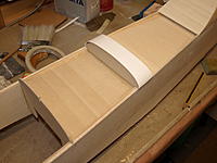
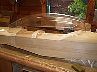
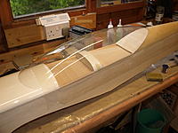
Early Xtra Wots had a higher rear deck (the foam/veneer moulding), the top line of the fuselage was square to the stern post. The rear deck is now lower, angles down from the cockpit to the tail. The fin remains the same length but the supplied fillet was for the early deck, hence the gap. Chris hadn't spotted this and nor had anyone else apparently! He's making a new part cutting jig and future kits will have the correct part. Added the extra wood, job done. We also discussed the elevator tip mod, this was to prevent flutter which I think is what broke the tailplane. Glued the tailplane parts together today and added the carbon reinforcement. Shaped the leading edges of the fin, rudder and tailplanes. While waiting for glue to dry I cut a section out of the fibreglass front deck as part of the two-seat conversion, cut with a razor saw. Also rough trimmed the canopy down to size, no trouble. Need to go shopping for bits and pieces soon as there really isn't much left to build. GB ImagesView all Images in thread
|
|
|
|
|
|
||
|
|
Quote:
|
|
|
|
||
|
|
|
|
|
Yes, it is fairly obvious when you look at it.
Makes it look better and the decking is easier to produce according to Chris. So glad that little mystery got solved! |
|
|
|


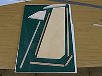









 The forward decking on mine is a quite thick fibreglass moulding, so it doesn't need any support from a hardwood strip; and where does the carbon fibre go in the tailplane?


