|
|
|
|
Thread OP
|
Build Log
Sebart MythoS Pro unboxing, assembly and maiden
Hi,
Here is my Sebart MythoS Pro unboxing, assembly and maiden flight that hopfully can be of interest to others. Comments how You have done things in Your F3A machine, or how You would have done things instead compared how I have done things below or other comments are welcome. This is my first 2 x 2M F3A machine so I have tried as best I could with that in mind. I have also a MythoS 125E that I flew last year so that is my background for assembly of more modern F3A style planes. I plan to fly Advanced (we name it "Nordic", slightly modified FAI Advanced class here in Nordic countries) this year with my MythoS Pro. I flew in same class last year with my MythoS 125E. I have a brief comparison between MythoS Pro and MythoS 125E as last part in this thread. Table of content: Part 1: Unboxing and comments. Part 2: Assembly and comments. Part 3: Maiden flight and comments. Part 4: Brief comparison MythoS Pro and MythoS 125E Enjoy! Edit: Most of the links to Robbe pages below is broken since Robbe has redesigned ther homepage sometime in December 2014. I will try to change the links to correct ones when they have their English version of their homepage up (they have it in German language only for the moment). Edit 2: Robbe went bankruptcy in 2015 so no Robbe links in this thread will work. /Bo |
|
|
Last edited by bossee; Jan 10, 2018 at 11:44 AM.
|
|
|
|
|
|
|
Thread OP
|
Part 1: Unboxing and comments
1.1 Arrival 1.2 Gear sources 1.3 Conclusions 1.1 Arrival At Christmas time a huge box arrived from Santa Claus. It arrived about one week after order without any damage to box or content. The box was huge and the materials and layers to protect the content was excellent. 1.2 Gear sources Then I had a period when I was thinking of suitable equipement and when I had decided on that it was ordered: - Futaba gear (receviver, servos, servo extension leads, current sensor, Telemetry-Box) was ordered from local Futaba reseller here in Sweden and also from Robbe in Germany (Sensor and Telemtry-Box). - Hacker and Jeti gear (motor, ESC, Anti-spark). - Falcon gear (Electric carbon V2 prop, Electric carbon spinner). - ThunderPower gear (LiPo 5 cell 5000 mAh). - Other gear (Motor mount, Dubro larger wheels, velcro, glues and some other things I had not in my shop for the assembly). In February gears started to drop in that I had ordered and in middle of March I had everyting needed to start the assembly and I then started to plan in detail for best approach to get the plane well assembeled for durability and easy maintenance. In middle of March I started the assembly more seriously and it was finihed end of April. I would say about 1 month assembly would have been possible in my case if I could have worked more uninterupted but it took in reality 1,5 month in my case to finish everyting including the final touch up with some decals and the usual small things one may want to do to on the plane to have it look nice. I have assembeled the smaller sisterplane MythoS 125E before (last spring, 2013) and although much of the assembly is similar it takes more time to assemble a MythoS Pro mainly because motor mounting, ESC mounting and battery floor building that all takes more time. Some of my sources for gear: I ordered my MythoS Pro from Lindinger in Austria (price OK, was in stock, free delivery and I had good experience with them in the past, and they are located in EU so no extra import fees etc since I live in Sweden and both countries are in EU sphere). More details what gear I use is in assembly part but here are my main sources: 1. Futaba gear http://www.robbe.de/rc-fernsteuerung..._from_store=en 2. Hacker and Jeti Gear: http://www.hacker-motor-shop.com/?shop=hacker_e 3. Falcon gear: http://www.falconpropellers.com/ 4. ThunderPower gear: http://www.thunderpowerrc.com/ 5. Other gear: Motor mount: http://www.f3alorenz.de/index-eng-home.htm 1.3 Conclusions Not much to complain about what is shipped in the box and the box itself (very good box that protect the plane fine during shippment). /Bo ImagesView all Images in thread
|
|
|
Last edited by bossee; Jan 10, 2018 at 11:45 AM.
|
|
|
|
|
Thread OP
|
Part 2: Assembly and comments
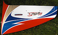
2.1 Wing 2.2 Stab 2.3 Rudder 2.4 Motor mount 2.5 ESC 2.6 Current sensor 2.7 Battery mounting "floor" and battery 2.8 Receiver and Backup Guard 2.9 Other 2.10 Conclusions assembly 2.1 Wing Sebart ships a weight chart for the various parts like wing, stab, fuselage etc, see picture in Part 1 above. Specified weight was 667 gram for both wings. Asssembeled with ailerons, servos (Futaba BLS551), 200 mm servo extension lead, wing nylon bolt, linkage, hinges+glue and decals I put on the wing halves the final weight is: Left wing 392 gram Right wing 386 gram Total 778 gram So my assembly to get the wings finished ready for flight added 111 gram. The actual balance will be finished in the air to see if I need to add weight to any of the wingtips. The build quality of the wing halves is according to my opinion high, not super quality but considering the price for the plane it is more then enough what one can expect (at least in my view). Covering is excellent with the Oracover (Ultracote in US) and I spent about 1 hour on each wing to iron on all surfaces on each wing+aileron to get the Oracover good adhered to the balsa surface. Time spent here mean almost no need to tighten any wrinkles later. I also "waterproofed" the open balsa structure on aileron front end on wing where hinge "ears" are located and also waterproofed hinge slots open balsa on the ailerons. I used Deluxe Materials "Aerocote" and also sealed some Oracover "seams" on sensitive areas to avoid they will lift from surface below like where thin lines ends. I also waterproofed the wing root end open balsa surface. Mounting the ailerons is easy but I replaced the Sebart white pin hinges that was supplied with new Robart 308 3 millimeter grey pin hinges. Little better quality on the Robart pin hinges in my opinion and I think they are little stronger also. I had to carv a little in the mounting holes for the hinges in the wing and aileron since the Robart pin hinges are just slightly thicker towards center. I used vaseline to protect hinge center pivot area while gluing the hinges and ailerons on the wing halves. I used Deluxe materials 1 hour epoxy for the hinges. Futaba BLS 551 (Brushless with metal gear, 44 gram each) was a direct drop in to the ready servo mounting hole in the wing. http://www.gpdealera.com/cgi-bin/wga...pgm?I=FUTM0564 It is listed as a "car servo" but works fine for wing servo also in my opinion. We will se if there will be any slop in the metal gear later. 200 mm servo extension cable in use for the wing to get comfortable length when mounting the wings to fuselage and the servo-connector I have mounted there. Original Sebart linkage is in use. I use Futaba/Robbe metal servo arm 15 mm No 8512 on the wing servos. http://www.robbe.de/alu-servohebel-1..._from_store=en Servo connector with servo lead on fuselage I use to connect wing servo connector is Robbe F1639: http://www.robbe.de/servokabel-mit-e..._from_store=en Nice wing bags for protection during transporttation is shipped with MythoS Pro (see image in Part 1 above). /Bo ImagesView all Images in thread |
|
|
Last edited by bossee; May 06, 2014 at 07:24 AM.
|
|
|
|
|
Thread OP
|
2.2 Stab
Stab build quality excellent, the Oracover (Ultracover) covering excellent from factory. Weight of both stab halves from factory was according to Sebart weight chart 222 gram. Assembeled with elevators, hinges+glue, linkage, servos (Futaba BLS 153, 26 gram each) each stab half is 147 gram. Carbon stab tube including two screws is another 11 gram. Total weight 147 x 2 + 11 gram = 305 gram. So my assembly to get the stabs finished ready for flight added 83 gram. Futaba BLS 153 (Brushless, nylon gear, 26 gram each) was not a direct drop in to the stab halves mounting holes, I had to carv away some plywood in one end since the BLS 153 is slightly longer then the mounting hole in the stab as shipped from factory. http://www.rc.futaba.co.jp/english/s...ts/bls153.html http://www.robbe.de/brushless-servo-..._from_store=en Futaba/Robbe metal servo arm 15 mm No 8512 (same as on wing servos) is used on the stab servos. http://www.robbe.de/alu-servohebel-1..._from_store=en No problems encountered for mounting the stab halves following Sebart assembly manual. Only missing part was screws that goes through the stab carbon tube, so I had to find suitable screws myself and ended up with a 3 mm wood screw 20 mm long that reach in to the carbon stab tube and go through it. Adjustment of stab works fine using the four hex screws on front part of stab root halves on upper and lower side. As starting point I set incidence on stab to 0.00 degree when wing had about +0.25 deg incidence measured with a Hangar 9 Angel Pro digital inclinometer. This Angel Pro is not accurate enough to set 0,25 degree so I had it set alternation (blinking) between 0.20 - 0.30 degree, that was the closest I could get. Then I turned the screw on underside of stab one turn in to get slight negative incidence (downforce) on stab. (when I tested in air I had to adjust this slightly back with less negative incidence to get rid of elevator down trim needed at maiden to get it flying straight, more about this under Point 3 Maiden below). With the screws through the carbon tube and adjustment screws tightened the stab is firm and only flex with fuselage (slightly) so this seems fine. It is also easy to disassemble the stab halves from fuselage for transportation: unscrew one of the screws that goes through the carbon tube on the underside of stab and then loosen two top (or lower) adjustment screws and then take away one stab half, then the other leaving the carbon tube in that stab half. The stab halves (with the carbon tube mounted one one of them) then fit inside the stab transportation protection bag that ships with MythoS Pro. /Bo ImagesView all Images in thread
|
|
|
Last edited by bossee; Jul 02, 2014 at 02:27 PM.
|
|
|
|
|
Thread OP
|
2.3 Rudder
The rudder is not much to tell about. It has the curved shape seen from above and the only modification I made was to use two Robart 309 4,5 mm pin hinges in the two middle hinges, the other two outer hinges was Robart 308 3 mm pin hinges. For rudder servo I use Futaba BLS 551 (same as wing servos) and it is mounted in tail. Rudder servo arm is Robbe metal arm 21 mm 8513. http://www.robbe.de/alu-servohebel-1..._from_store=de In rudder servo mounting hole in fuselage I reinforced the hole with a 2 mm plywood frame inside and added another 2 mm strip of plywood where the servoscrews goes through. /Bo ImagesView all Images in thread |
|
|
Last edited by bossee; May 06, 2014 at 03:54 AM.
|
|
|
|
|
Thread OP
|
2.4 Motor mount
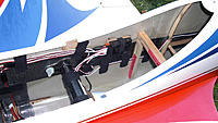
Mounting the motor was the most difficult part and took me about one week before I had everyting adjusted and mounted as I wanted it. I had checked with another MythoS Pro owner here in Sweden and mounting motor flat to nose ring was a good starting point according to him so that I did. Motor in use is Hacker Q80-14XS F3A. http://www.hacker-motor-shop.com/e-v...&c=2986&p=2986 Motor mount in use is a carbon one I bought from F3A Lorenz in Germany: http://www.f3alorenz.de/index-rc-flug-zubehoer.htm (follow the link "Motorbefestigungen für Verbrenner oder Elektro" on that page) Carbon Motor mount (German: Kohle Motorträger) nr 382 (49.90 Euro). Rear carbon support (German: Hintere kohle motorabstütsung) nr 381 (47.90 Euro). First I made nose ring template from stiff paper with 82 mm spinner backplate as template so I had correct nose ring diameter and center hole plus vertical and horizontal reference lines. Then I made a 2 millimeter plywood nose ring with 82 mm spinner backplate as template so I get suitable space between spinner backplate and fuselage nose ring. I measured very carfully since drilling in fuselage is a thing I only want to do one time (correctly). With everyting aligned it was just to drill the holes and countersink the screw heads. The carbon motor mount had to be shimmed somewhat with some extra plywood to get exact fit of motor distance to nose ring. I think I got this exactly aligned with nosering and it is 2 millimeter clearance between spinner backplate and nose ring now, all around the nose ring. I also bought a carbon rear support for the motor and after making templates of stiff paper I made the rear support "ears" in fuselage of 3 millimeter plywood with a 4 mm blind nut epoxyed into the it and two 4 millimeter nylon bolts holding the rear support in place. There is a metal rod together with the rear carbon support that fits exactly in the Q80-14XS rear ball bearing for this rear support. Rear support plywood ears was glued with slow curing ("24 hour") epoxy with some flock fibres to make it thicker and fill some gaps. I'm very pleased with mounting of the motor. I do not think I need to adjust or change anything on this. One can easily do a motor mount and rear support out of own good multilayer plywood to save money but I selected the ready made carbon motor mount to get things done little quicker (maybe saving some weight also and perhaps little stronger also). One funny thing happened when I was mounting the motor: One the evening when I was going to sleep I noticed that my watch had stopped. Strange I thought, it was not so long time ago batteries was changed in the watch. Next day I went to the watchmaker and said I wanted battery changed because my watch had stopped. Went back to work to pick up the watch later when finished for the day at work. Little later the watchmaker phoned and said it was no problem with the battery and said the clock must have been near a magnet and that way stopped. Hm... I said I could not remember that I had been near any magnet. Anyway battery was changed and watch retested for pressure (watertight clock) and 300 SEK ($45) later I had a working watch again. When I got home I was thinking what could have stopped the watch. Then I put one and one together - an electric motor has magnets and a Hacker Q80 has pretty strong ones. I had been holding the Q80 motor with my left hand where I have my watch and bang the magnets in the motor killed the watch. So watch up for this. /Bo ImagesView all Images in thread
|
|
|
Last edited by bossee; Jun 22, 2014 at 05:37 PM.
|
|
|
|
|
Thread OP
|
2.5 ESC
ESC in use is a Hacker/Jeti Master Mezon 130 with BEC. http://www.hacker-motor-shop.com/e-v...&c=5446&p=5446 I use the BEC on the ESC (together with a Scorpion Back up Gard battery). Although a little heavy ESC (155 gram) I prefer to have some current margins. The varoius versions of the lighter Mezon 90-95 would work also. I use same ESC in my MythoS 125E also so that was another reason I selected Mezon 130 with BEC so I could use the one in my MythoS 125E as spare ESC for my MythoS Pro. I mounted the ESC close to the lower air intake in fuselage, mounted it on two 4 mm carbon tubes with plywood mounting support for the mounting ears with rubber groomets on ESC. When You look from front in the air intake the ESC is nicely aligned so air will flow over the heat sink on ESC and then air continue back towards exit airhole in fuselage floor. The settings in the ESC is for the moment set exactly as I have in my other Mezon 130 ESC in MythoS 125E where I have a Hacker A60-7XS - same motor settings and brake settings etc. It seems to work fine with my Q80-14XS also as far as I have seen during the 10 first flights of MythoS Pro. Both ESC has same cable lengths and connectors so I can swap them between the machines without need to make any changes in the settings for the ESC. Both ESC has same firmware 1.27 also. I checked with Jeti Box the Mezon log after some of the maiden flights with the Falcon prop I use and it was logged: Max RPM: 5920 rpm Max current: 70 amp (Curent sensor showed 68 amp) Max temp: 31 deg Celsius (it was about 8-9 deg Celsius out when I made the last logged flight) Min voltage flight battery: 35.5 volt Max BEC current 1.4 amp Max consumed capacity: 3780 mAh (motor running time 10:06 min) Status (error codes - F,IM, PB, PL, M): 0 Alarm (excceding limits set for alarm - ACCU, BEC, T, CAP, I, TB): 0 /Bo |
|
|
Last edited by bossee; May 09, 2014 at 08:46 PM.
|
|
|
|
|
Thread OP
|
2.6 Current sensor
New to me is current sensor, I have not used one before. Since I have no FASSTest radio (I have a Futaba 14MZ, FASST) I had to buy a reciever that can handle telemetry and also a display that can show on display and sounds the telemetry data. Reciever I use is a Futaba/Robbe R6308SBT that has telemetry and SBUS2 port(needed for current sensor). The current sensor is a Futaba/Robbe F1678. http://www.robbe.de/stromsensor-150a..._from_store=en I have also an optional voltage cable connected to flight battery and connected to the currect sensor so I can see the flight battery voltage on the Telemetry-Box. http://www.robbe.de/anschlusskabel-e..._from_store=en The current sensor installation is not that difficult but the soldering of the battery cable in the board inside the sensor was the trickiest part (a cold soldering here is a no no). I placed the current sensor behind the ESC just in front of landing gear so the vent-holes in the current sensor had fresh air flowing through to cool it and then let the air exit on the fuselage main air exit hole behind it. The current sensor is registered in the Telemetry-Box (and Telemetry-Box is linked to the Futaba R6308SBT receiver). My main interest is to keep track of mAh consumed and I set max value to 4000 mAh in the sensor settings in the Telemetry-Box and when that was reached the speech said that I had reached this limit. I also see on display in Telemetry-Box exactly how many mAh is consumed. So this seems to work fine. I will upgrade the current sensor firmware so I can assign a switch on transmitter to zero the mAh count easier (now I have to press reset button on the current sensor to reset that). Current sensor weight is 19 gram. /Bo ImagesView all Images in thread
|
|
|
Last edited by bossee; May 05, 2014 at 09:21 AM.
|
|
|
|
|
Thread OP
|
2.7 Battery mounting "floor" and battery
As battery mounting floor I used the Sebart supplied glassed balsa plate. I made two supports like an inverted U so it has the floor and then sides as extra reinforcement. Reinforced it underside with thin plywood so flight battery straps would not have any chance to go through it on high G loads. I use Hacker battery straps (400 mm long). http://www.hacker-motor-shop.com/e-v...&c=4596&p=4596 I have a discussion as how high vertically I should mount the battery in the fuselage here: http://www.rcuniverse.com/forum/elec...ythos-pro.html I checked the vertical CG and ended up reasonably well I think. The battery floor/support is glued with 24 hour epoxy. I let the plus and minus cables from ESC->Current sensor->Battery go between the battery mounting supports and made a thin plywood plate with rubber grommets that cables go through (cable and grommet can be deattached from the mounting/support plate). Battery I use is ThunderPower G8 25C 5 cell x 2 5000 mAh. Today it is ProLite X: http://www.thunderpowerrc.com/AIR_BA.../TP5000-5SPX25 Probably 4400 mAh 10 cell can be enough, that is what Sebart has listed as recommended flight battery. /Bo |
|
|
Last edited by bossee; Jan 10, 2018 at 12:40 PM.
|
|
|
|
|
Thread OP
|
2.8 Receiver and Backup Guard
Receiver used is Futaba/Robbe R6308SBT FASST telemetry. http://www.robbe.de/empf-r6308sbt-fa..._from_store=en It has 8 slots for servo connectors, one SBUS and one SBUS2 connector. 18 ch, weight 13 gram. I mounted it on fuselage with velcro on a thin plywood plate that was glued to fuselage side slightly behind the wing tube. Since the Current sensor is used it is not possible to run the reciever in high speed mode, so it is set for normal mode. I use the Futaba Telemetry-Box also with my 14MZ radio so the Telemetry-Box must also be binded to the reciever, it is a procedure one follow in the user manual for the Telemetry-Box. To get support for the current sensor the Telemetry-Box must have firmware 1.003 installed in Telemetry-Box and it can be downloaded from Robbe homepage (I installed that upgrade): http://www.robbe.de/telemetry-box-2-..._from_store=en In Telemetry-Box it is settings for receiver and the sensors used that user can customize (see user manual at above link). So far the telemetry has worked fine. If the Master Mezon BEC would fail and the Scorion Backup Guard will kick in I will get an alarm since the voltage is then lower then min volt I have set set in Telemetry Box (Scorpoin Backup Guard kick in if voltage drop below 5 volt). As an extra battery if the BEC fail for some reason I use Scorpion Backup Guard, that is a 2 cell 500 mAh LiPo battery with special circuitry so when it is on it do not supply power to reciver+servos unless main source battery drop below 5 volt (or dissapear completely). It is connected to the receiver. I have used a Backup Guard in 2013 season in my MythoS 125 also and it has so far worked without any problems. It is just to hope it will do it's job if the BEC should fail. http://www.scorpionsystem.com/catalo..._Backup_Guard/ /Bo |
|
|
Last edited by bossee; May 30, 2014 at 04:40 AM.
|
|
|
|
|
Thread OP
|
2.9 Other
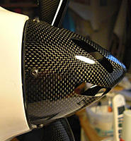
Fuselage quality: In my opinion the fuselage is well made. I can not see any shortcuts taken and the ARF maker has made an excellet job with it. One thing I thought was a little weak was the wing tube holder in the fuselage, it was so thin and fragile that I decided to use one layer of carbon fiber+epoxy around it to make it stiffer. After that it feels strong and I hope it will be no problem with that in the future. Fuselage is light and I can imagine it will not tolerate much abuse. It is beautifully painted with a layer of clear coat as last finish. I have nothing to complain about. I hope the plywood landing gear mounting plate will be strong enough so it will not be as on my MythoS 125E where I had to strengthen the mounting plate after it got "soft". Landing gear: Seems also to be well made but the wheel axels nut facing towards the wheel came loose on both axels when I tightend the axels to the landing gear so the quality on these was not so good. I fly on rough grass flying field so I replaced the wheels with Du-Bro Super Light wheels 70 mm / 2-3/4" (no wheel pants is used): https://www.dubro.com/collections/ti...er-lite-wheels Propeller and spinner: I use Falcon electric carbon V2 prop 20,5 x 14.5 inch, it is very light - only 37 gram. http://www.falconpropellers.com/prod...n-electric-v2/ With Hacker Q80-14XS F3A motor I get about 5900 rpm in the air at full throttle (on a cold day at 8-9 deg Celsius, on warmer days it will probably reach 6000 rpm). Spinner in use is Falcon electric carbon 82 mm - also very light, only 23 gram. http://www.falconpropellers.com/falcon/carbon-spinners/ Canopy and small top wing: Excellent quality but... Mounting of the canopy with top wing could have been easier, now it is 3 screws - two that can be screwed by fingers on side of canopy and one on top of small wing that needs a hex screw. It works but takes a little extra time to mount the canopy with top wing. I will probably do something about the top wing screw so I can use fingers only to tighten a screw there. Wing bolts: The nylon wing bolts are not mectric and I have so far not found any spare wing bolts (good to have just in case). Close to metric M6 mm thread but it is not (I have tried). Inner diameter thread is about 5.2 mm and outher diameter thread is is about 5.8 mm. Still looking for wing bolts to have as spare. /Bo |
|
|
Last edited by bossee; Jan 10, 2018 at 11:51 AM.
|
|
|
|
|
Thread OP
|
2.10 Conclusions assembly
Build quality of MythoS Pro ARF seems to be high and I have nothing to complain about really. Can't compare it to an Axiome plane or similar in quality but for the rather modest price the MythoS Pro ARF has it is good quality in my opionion. Assembly of plane is not difficult but one has to be accurate when mounting the various things. Motor mounting was the most difficult part in my opinion. For the weight concious person it is possible to get it lighter that my plane that has weight of 3759 gram without flight battery, and with flight battery it is 4930 gram. Lighter servos, SBUS to tail servos (to save on servo cable weight - 1 servo cable to tail instead of 3), lighter ESC, smallar flight battery (4400 mAh should be enough saving about 140 gram with ThunderPower G8 batteries compared to 5000 mAh), shorter ESC and battery cables, no current sensor (adds about 20 gram in my case with Futaba current sensor). /Bo |
|
|
|
|
|
|
|
Thread OP
|
Part 3: Maiden and comments
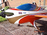
3.1 Photos before and after maiden 3.2 Initial trimming and conclusions (after 10 flights) 3.1 Photos before and after maiden Before maiden I took some photos just in case anything should happen so I have at least photos left of all work made of assembly this MythoS Pro. I took some photos in my garden day before maiden, see below. At flying field I also took some photos before and after maiden, see below. 3.2 Initial trimming and conclusions (after 10 flights) Maiden flight was no trouble really but I had to make 3 clicks to trim down the nose and 4 clicks right aileron trim. The elevator trim I readjusted the stab adjustment screws with until it flew level with elevator straight (no trim needed). The aileron trim I'm not sure what to do about (mabe adjust incidence slightly on left or right wing half). Plane has a slight tendency to go to canopy in knife edge - I have to think more how to adjust that. I think it dives a little to much inverted (little to much down elevator is needed in my opionion) - I will try with CG more to the rear and see how much that help to start with. Elevator and rudder throw I increased a little and aileron I have so far let it have the throws I set initially. Loops, stall turns and roll rate feels rather good now. Verticals and downlines is reasonably straight. It will be many more flights before I will be satisfied with the trimming so I will take this step by step and only change one thing at the time and see what happen. /Bo ImagesView all Images in thread
|
|
|
Last edited by bossee; May 06, 2014 at 04:07 AM.
|
|
|
|
|
Thread OP
|
Part 4: Brief comparison MythoS Pro and MythoS 125E
Since I assembeled a MythoS 125E in spring 2013 and then flew it all season 2013 I thought I would do some comparison of it against MythoS Pro. Price, quality and value: MythoS Pro ARF is close to 3 times more expensive as MythoS 125E (here in Europe). Motor, battery, ESC etc is also rather much cheaper for a MythoS 125E. Wing+stab is very similar on both planes, just wing and stab area that is little less on MythoS 125E. Fuselage is balsa+plywood covered with Oracover on Mythos 125E and on MythoS Pro it is glass fuselage that is overall better quality and looks nicer with it's painted finish. Better landing gear on MythoS Pro with built in gear fences (on MythoS 125E You have to glue balsa fences on the landing gear). Canopy and small wing has better mounting on MythoS 125E in my opinion (only two screws on 125E). The deattachable cowl on MythoS 125E makes it easier to do maintenance and motor mount is ready for You on 125E. For MythoS Pro You have to arrange Yourself for suitable motor mount as well as ESC mount and battery mounting floor. You really get much for Your money on both planes but MythoS 125E gives slightly more for the money in my opinion. 125E flies really good and flies the Advanced class very good. If You are going to fly FAI F3A P-1x schedule a MythoS Pro is more logical selection. When You add everyting needed to get both planes ready to fly and use Hacker motors, Hacker ESC, ThunderPower G8 LiPo (as I use) and other things needed to complete the planes You end up with considerable cost. In my case I estimate the MythoS Pro is probably at least twice as expensive to finish ready to fly compared to my MythoS 125E. But both planes can be equipped with less expensive accessories of course. Hinges and Control surfaces: Both planes use pin hinges but MythoS Pro has rounded leading edge on control surfaces that go slightly into wing/stab/fin and have pivot point slightly into the control surface that should give better sealing. I use the Sebart pin hinges on my MythoS 125E but replaced them with Robart pin hinges on my MythoS Pro. Both planes has the curved out shape of rudder but only MythoS Pro has also curved out shape on elevators, on MythoS 125E the elevators has flat surface. Other then that it is very similar on both planes regarding the control surfaces. Flying: Since I have only made 10 flights with my MythoS Pro so far and have not trimmed it fully to my satisfaction I can not say really how good it will fly. But I have seen other top flyer in my country fly MythoS Pro and it flies without doubt very well. On my MythoS 125E I had about 300 flights last season and I have been very pleased with how it fly Advanced (here Nordic) schedule. No bad behavior really that I have discovered. Transportation: Mythos 125E: Fuselage length 1900 mm, wingspan 1800 mm, wing area 61 dm2 (stab area unknown) MythoS Pro: Fuselage lenght 1990 mm, wingspan 1880 mm, wing area 66 dm2 (stab area 19 dm2) The fuselage length on MythoS Pro, although only 90 mm longer, makes it more difficult to transport in a car. But the stab halves are detachable on MythoS Pro (and also on MythoS 125E) rather easy so with them removed it will be easier to find room for the fuselage in a normal seize cars. In my car (a Volvo V70 2014) I can have the stabs mounted and the plane still fits the baggage compartment if I place it diagonal. Assembly time: For me it took close to twice the time to assemble my MythoS Pro compared to my MythoS 125E. I have no problem to recommend MythoS 125E both regarding the assembly and flying capabilites, and for MythoS Pro I think an average good builder should be able to assemble it rather quick but it requires more skills to assemble MythoS Pro. So far I'm satisifed with the flying capabilites I have seen of my MythoS Pro but time will tell how satisfied I will be when I have it trimmed to my satisfaction. I will report back what my control surfaces throws are when I have trimmed in the plane little better. I have the center of gravity at 200 mm behind wing leading edge where wing root meet fuselage now but I will try to move the CG to 210 mm and see how I like that also. Note that in the pictures below on my MythoS 125E I have a painted (inside) canopy, it is a clear canopy from factory. It is painted inside with Pactra spray can: https://www.rcgroups.com/forums/show...&postcount=435 Hope You liked the description of MythoS Pro etc above. /Bo ImagesView all Images in thread
|
|
|
Last edited by bossee; May 09, 2014 at 08:57 PM.
|
|
|
|
|
Thread OP
|
Hi,
I decided to move the flight battery mounting back a little since I could not get all back to 210 mm center of gravity with the original location I made. So I had to bite the bullet and use an x-acto thin jig saw http://xacto.com/products/cutting-so...r-Saw-Set.aspx and managed to saw this out and I then moved the battery holder about 40 mm back. It took a whole evening to do this. I can now move the flight battery from CG 200 mm to 210 mm (I know I will never use 190 mm CG since it will be to nose heavy for me). I also upgraded the Futaba/Robbe current sensor with new software (firmware) so I now can use a switch on transmitter to reset mAh count to zero. Channel DG1 is used in Futaba radios to control this reset. Only DG1 can be used, and I used the default switch linked to this channel in my 14MZ and this is switch "SD" on the transmitter top right corner. It is a 3 position switch and in pos 3 (selected two times in row) the mAh counter in the current sensor is reset to zero (that can be seen in Telemetry-Box display). This works fine. SD switch on my transmitter is a switch I never use for anything else and the 3 position plus You have to select pos 3 two times to reset makes the SD switch suitable I think. The software 2.0 for the Futaba/Robbe current sensor upgrade is available at Robbe homepage and it is just to download the EXE file and double click on it and it will extract to several files including a upgrade instructions in PDF. A special a program is used that one install that perform the actual firmware upgrade with a firmware file and one need a USB cable with "micro" connector on it (not the similar "mini" connector that is slightly too large). To reach the selecting mode efter the upgrade is finished it is important to to press reset button on the current sensor when the current sensor is just starting up (before the green LED is on) and the LED is then blue, in that moment one can press briefly to scroll between the 3 modes and when desired mode (in my case I wanted mode 3 since I wanted switch on transmitter to reset mAh) was displayed I hold the reset button and it will be the saved mode. You can then see after this, when the current sensor is started up, how many blue blink there is shown and that way what mode it use. It worked fine for me to make the upgrade and to set desired mode. Software download: http://www.robbe.de/stromsensor-150a..._from_store=en (under Downloads) Edit: Conatct med if You need the downloads. Update instructions for 150 A current sensor, software update version 2.0 The software of the 150 A current sensor No. F1678 has been revised, and the following functions have been added or modified. Resetting the capacity display Three are three methods of resetting ("zeroing") the capacity: Mode 1: operating the RESET button while the sensor is active (LED glowing green). Mode 2: automatic reset after switching on the sensor's power supply via its SBUS lead. Mode 3: operating a user-selectable switch on the FUTABA transmitter, which is assigned to switched channel DG1 only. Operating the switch twice (e.g. pressing the button twice) within three seconds while the sensor is active (LED glowing green) resets the capacity (sets it to zero). Note: Mode 3 can only be used with FASST Multi / FASSTest systems. Displaying / selecting the modes When the sensor is switched on, the LED flashes blue to indicate the currently set mode: One flash corresponds to Mode 1, two flashes to Mode 2, three flashes to Mode 3. If you briefly press the RESET button during this flashing phase, the sensor remains in display mode, and the indicator for the currently set mode is repeated. Repeated brief presses of the RESET button "scroll" through the modes. Holding the RESET button pressed in confirms the currently indicated mode; the LED then glows green or red. The weather has been crap so far this week, rain and cold so no flights made. Today no sunshine and some rainshowers so far. As soon as better weather I will fly more with my MythoS Pro. /Bo ImagesView all Images in thread
|
|
|
Last edited by bossee; Jan 10, 2018 at 11:55 AM.
|


