| Thread Tools |
| This thread is privately moderated by Jack Crossfire, who may elect to delete unwanted replies. |
|
|
|
|
Thread OP
|
Discussion
XV-11 lidar begins 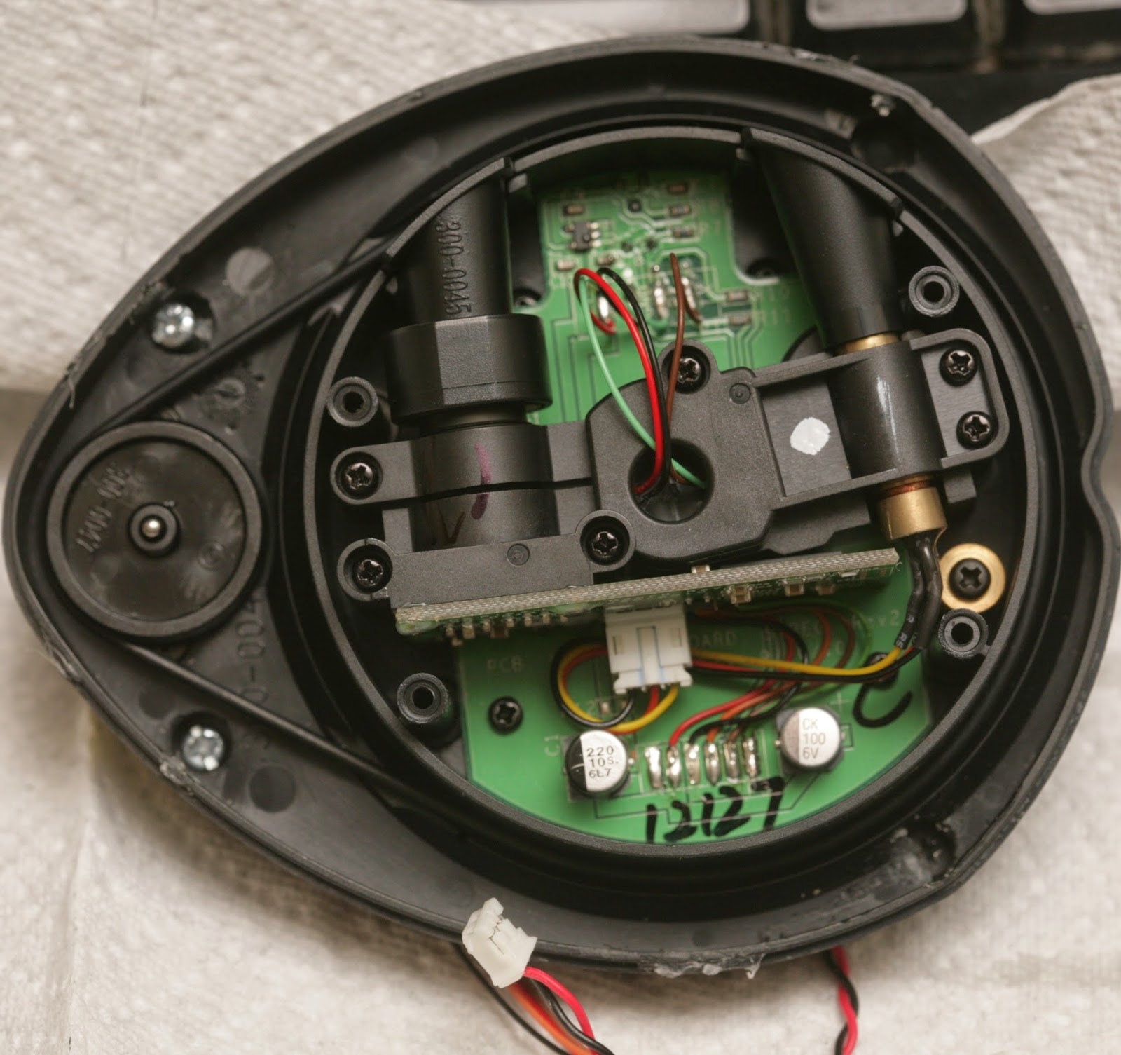 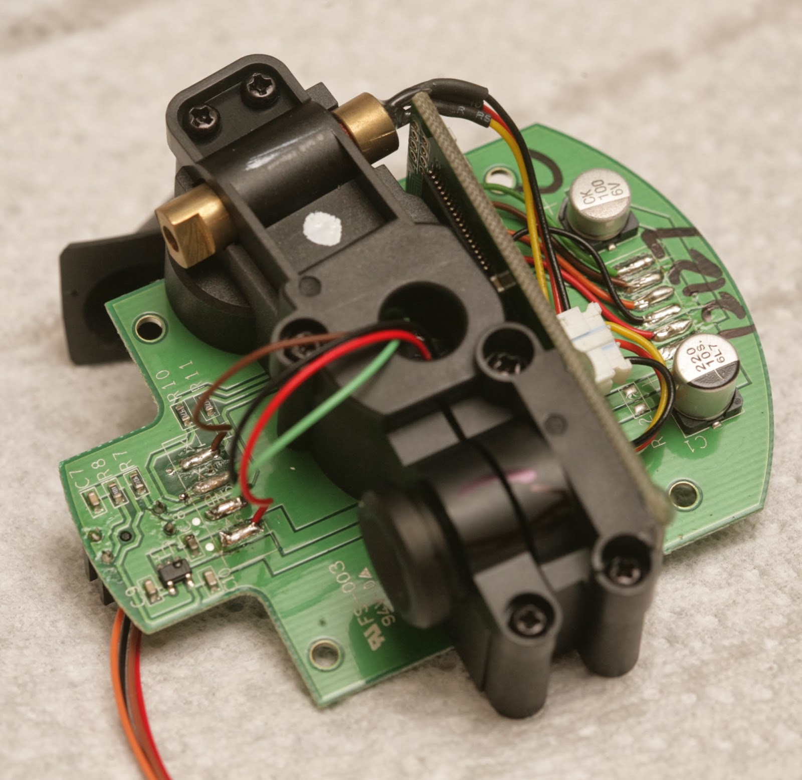 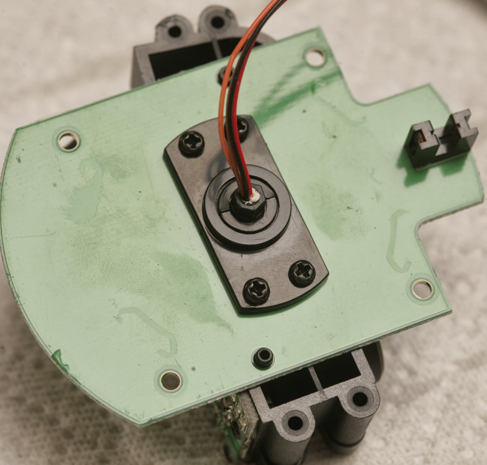  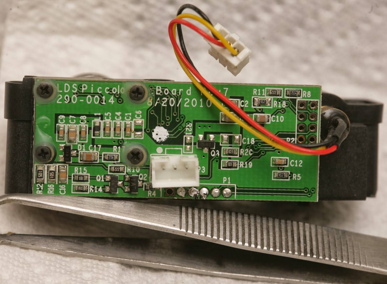 It's definitely a Silicon Valley startup product. There's no emphasis on miniaturization. It's loaded with unnecessary, cosmetic plastic. The PC board is 1/16" thick. It uses 1990's era 0603, 0805 components, full size JST connectors. The laser & camera are giant. It's bare minimum set top box parts repurposed for lidar. The sensors came from fully assembled vacuum cleaners, since they still had the screws with threadlock. Since it clearly was too heavy to fly in its spinning form, it was time to extract the bare ranging element. The ranging element weighs 30g. The PX4flow weighed 17.5g. The board has 5V labeled, but it's converted to 3.3V by an LDO. red: 3.3V black: GND orange: photodiode output 3.3V when interrupted 0V when clear brown: TX data going into device green: RX data going out of device A 220uF cap filters the 5V power. A 100uF cap filters the 3.3V power. The UART signals have 4.7k resistors. 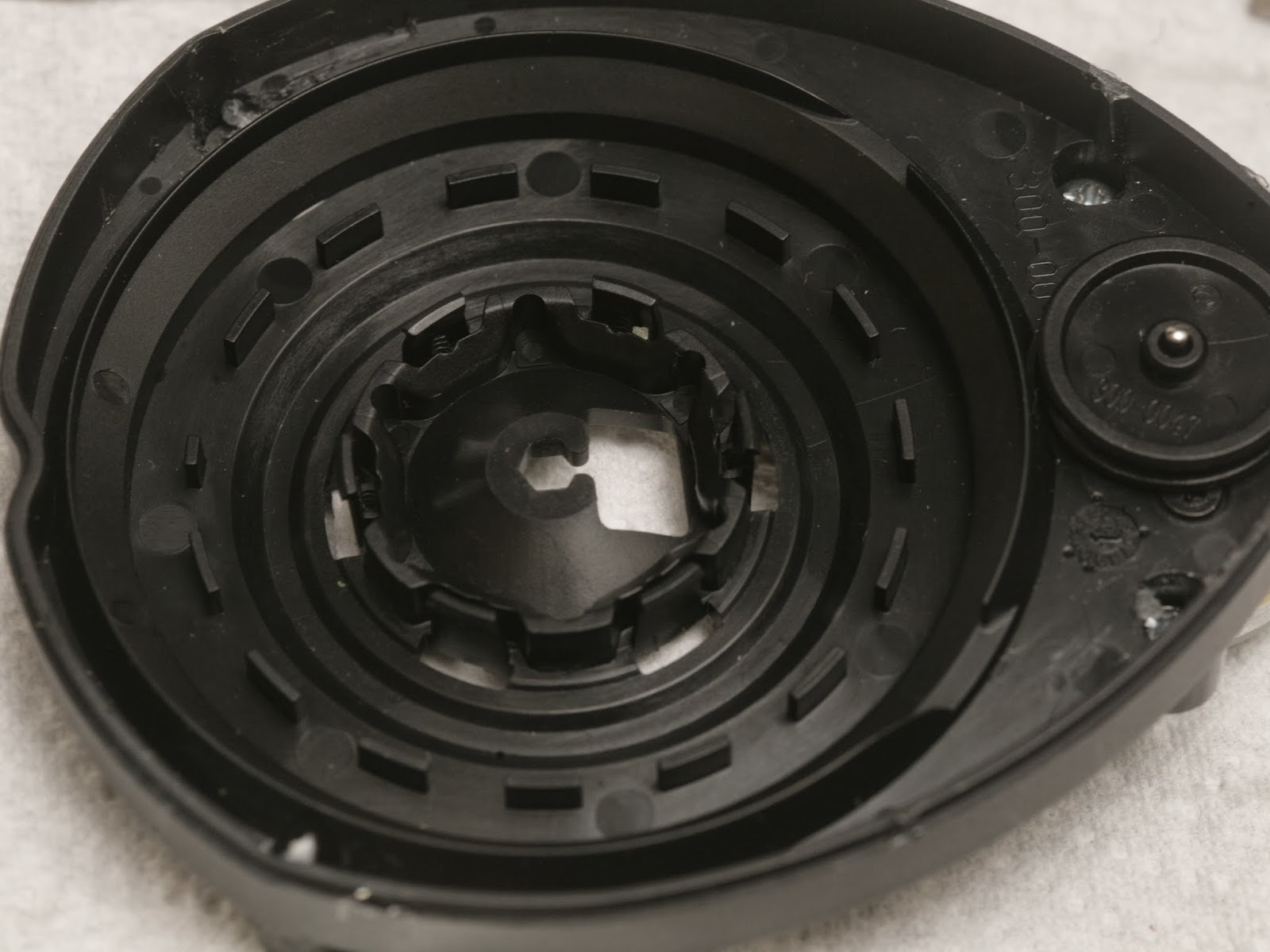 The photo interrupter pattern has 15 interruptions per revolution with a shorter one to tell it where the azimuth is.  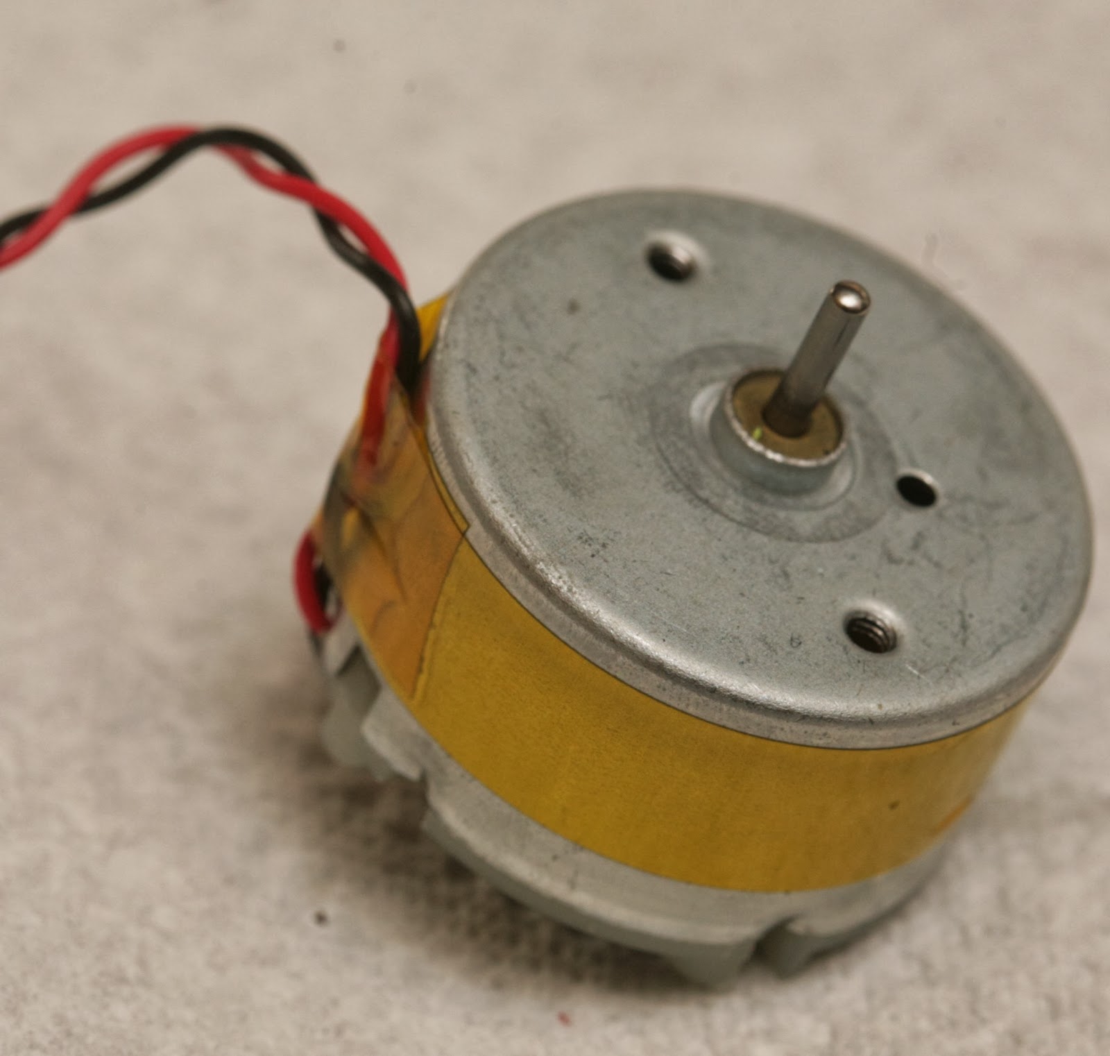 There's a decent quality bearing & brushed motor. 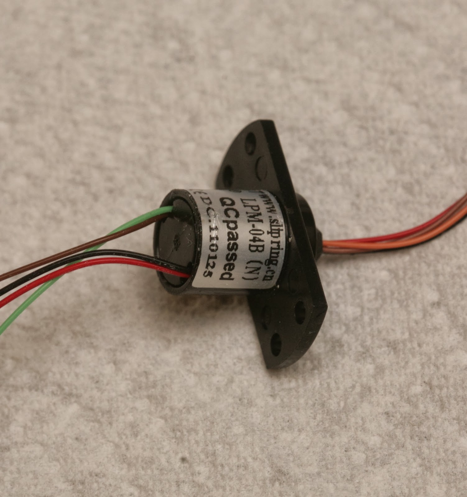 The slip ring would be very useful if you're into synthetic aperture radar & have a way to drill perfectly aligned holes. The lens is variable focus with 1 screw clamping it down. Once unscrewed, it becomes loose. There's no way to focus it without an unknown debugging mode. 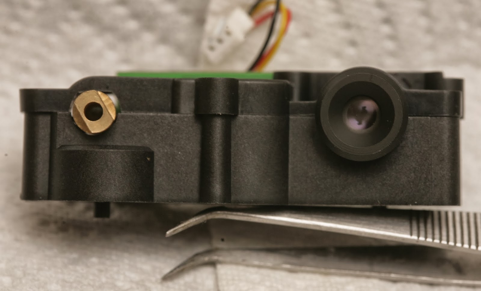 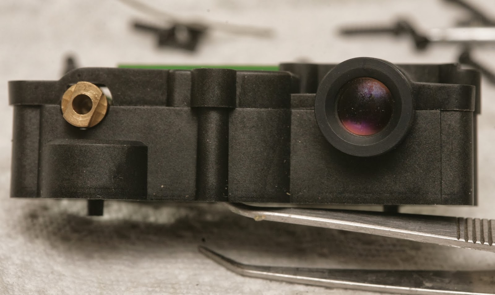 2 of the modules had smaller lenses. 1 had a larger lens. 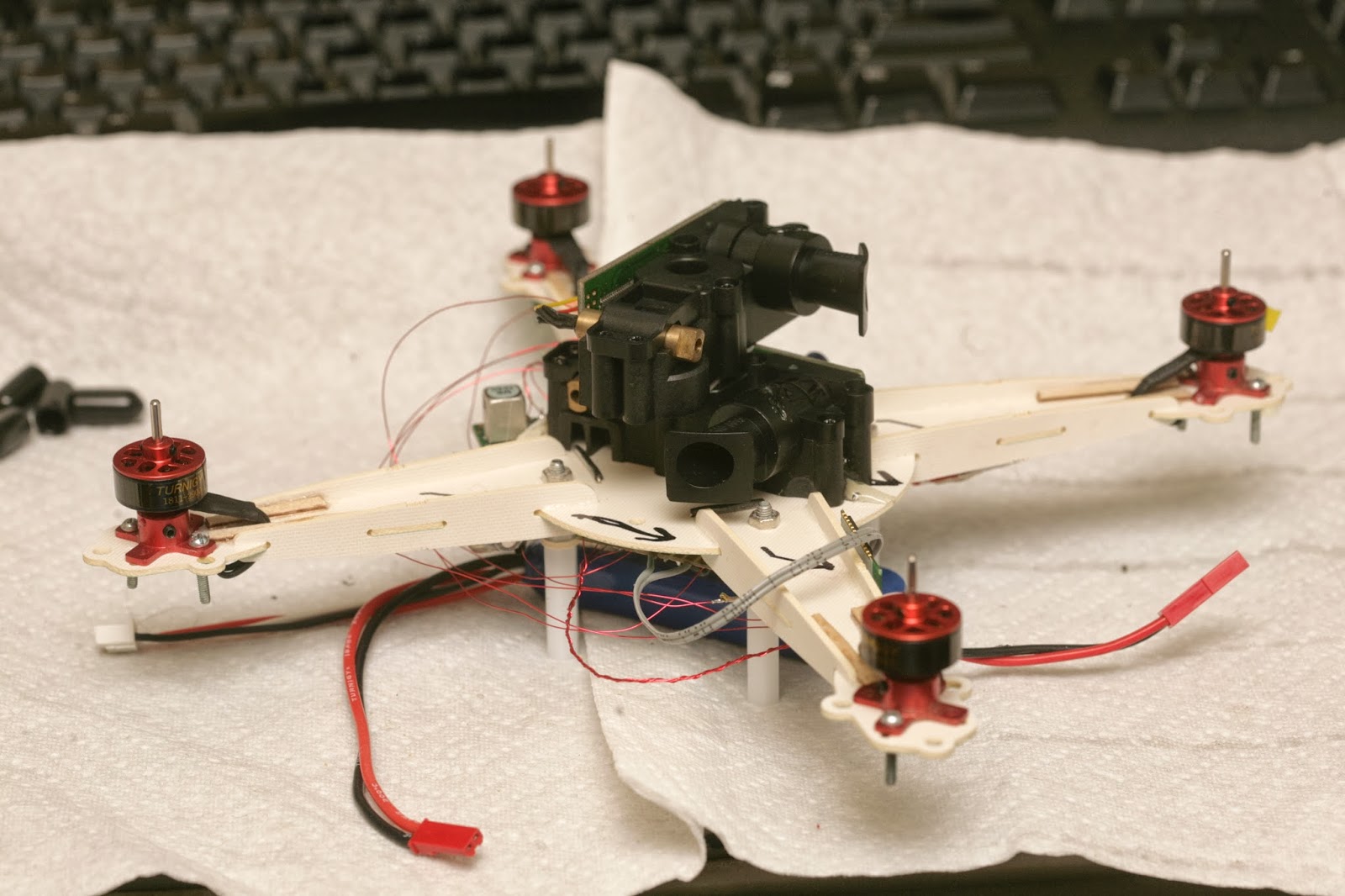 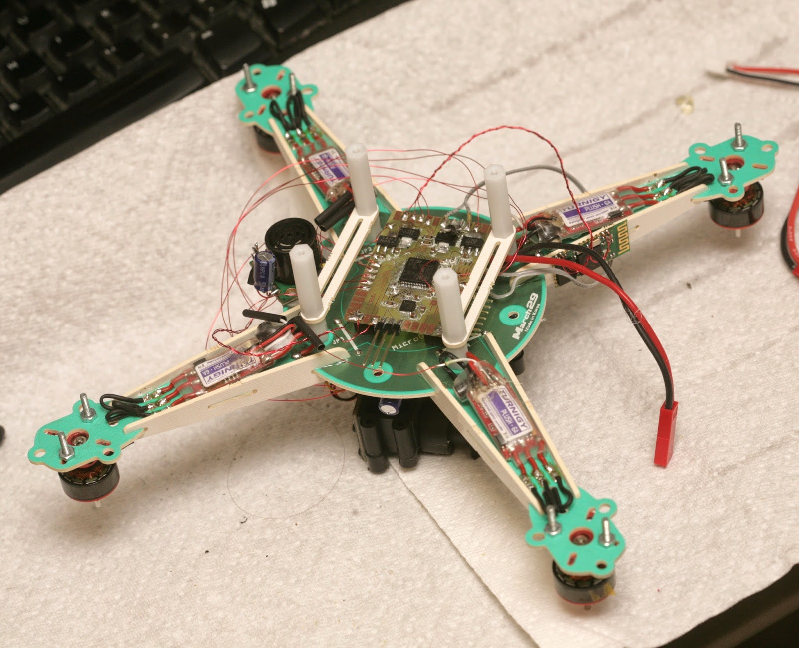 A 1st attempt at attaching everything led to a huge 250g brick. It's going to be really slow. There's no durable way to attach the 2 LIDAR modules. Random bits of information about the XV-11 lidar: http://xv11hacking.wikispaces.com/ |
|
|
Last edited by Jack Crossfire; Mar 08, 2014 at 08:02 PM.
|
|
|
|

