|
|
|
|
Thread OP
|
Discussion
The Mobius 1 ActionCam Support Thread (Posts #1-#7 mandatory reading!)
Thread Usage Protocol
This thread is only for the original Mobius M1 ActionCam (a.k.a. M1), NOT for it's updated M1S model which has it's own support thread here. This thread is hosted by M1S users, not the camera developer, and is part of a radio controlled model web site in a Forum dedicated to Aerial Photography. As such, the content of this thread is intended to focus on the M1, NOT other cameras from this same developer. A basic comparison with the other Mobius cameras can be found in this User Thread. That said, the M1 is unique in it's small size, weight, capabilities, and price point, making it ideal for many other uses to capture action video. Therefore many persons interested in the M1 for purposes other than aerial video may be directed here for camera support by various vendors, and you are welcome here for the purpose of helping you with the camera's operation. Issues with adapting the camera for other uses should be discussed in more appropriate forums, e.g.:
ALL users of this thread are requested (and expected  ) to adhere to the following posting protocol: ) to adhere to the following posting protocol:
Thanks in advance for your cooperation! |
|
|
Last edited by Tom Frank; Dec 04, 2022 at 04:19 PM.
Reason: Added link to comparison with other Mobius cameras
|
|
|
|
|
|
|
Thread OP
|
Mobius ActionCam Vendors and Specs
Mobius ActionCam Vendors and Specs
The Mobius, by the developer of the highly successful #16HD "808-style" keychain camera, is a logical progression to the more capable 1080p level of video hardware. The features that made the #16 such a hit, namely small, light, configurable, great video, and low cost are being extrapolated and expanded to match the capability of the new hardware. The firmware will take many months to mature and incorporate all the capabilities of the new hardware, but the developer is actively pursuing this goal while watching this thread for user feedback on issues that might need fixing. Vendors You are advised to only buy your Mobius from a developer-verified source. The following web stores have been verified by the developer as selling the real Mobius camera, replacement parts and accessories with a commitment to customer satisfaction, both before and after a sale, if any problems are found when the hardware is put into service and not caused by user abuse, crash damage, etc. If parts are not listed on their sites, use their web site email contact link to request what you need. They will respond promptly with information of how to buy them. They all use direct PayPal payment. The China eBay sellers work directly with the developer and will usually have the lowest delivered prices. The other re-sellers may offer quicker delivery depending on your location. Direct Sellers: China: eletoponline365; digitalele889Re-sellers: China: HobbyKing (Hong Kong); BangGood;Prices can vary from one vendor to the other and depends on what is included in different accessory packages. The cost from the China direct seller eBay outlets will be nominally about $70 US with free shipping. Non-verified sellers may be selling fake imitation cameras at seemingly bargain prices, and you should be wary of buying from them. NOTE: Both users and vendors are expected to abide by this forum and thread vendor communication protocol. Memory Cards Class 4 memory cards from popular manufacturers provide the best compatibility with this camera and are recommended. Class 6 and Class 10 cards, at best, do NOTHING to improve the camera's video and cost more, and at worst, they may not work properly! ALL MEMORY CARDS should be formatted using the camera's internal formatting routine for best compatibility! . If you are uncertain about what kind of memory card to buy, order one from the camera vendor when you place your order. Case Design The camera has a modern case design precision molded of rugged high-density plastic to house the upgraded CMOS imager, DSP chip, and larger battery. Three buttons (power, mode, and shutter) are provided to toggle various functions, with 4 LEDs for visible feedback on the cameras operation. The top of the case has two exposed metal heat sink surfaces protruding through the case heat dissipation from the DSP and memory chips. The case has a shallow groove extending around case upper and lower joint line. This enables the case to be securely slid into a mating base piece for a variety of mounting hardware options (more info below). This shows a size comparison of the Mobius with the current #16 camera in its current flat-bottom case and wide angle lens. The basic camera weighs approximately 39 grams (without lens cap) and measures nominally 61mm (L) x 35mm (W) x18mm (H). When inserted into it's mounting base plate, the overall dimensions (without the mounting screw insert) are 63mm (L) x 38mm (W) x 22mm (H). 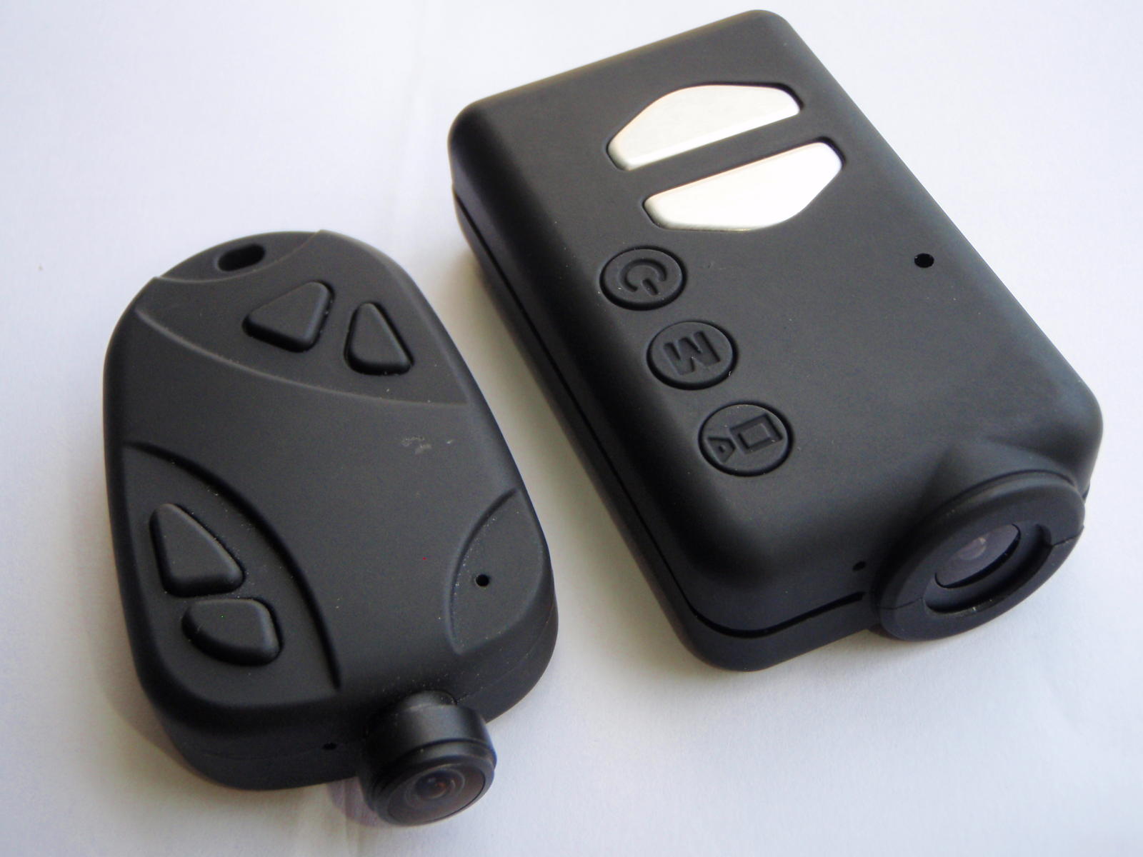 . . The inside of the case top and bottom has precision molded rib structures to accurately position and securely hold the CMOS/lens module.  In Oct. 2014 the case design was changed very slightly with a wider top LED view port equipped with a plastic "light pipe" inside to make the LED's much more visible. The CMOS module slots were also had very minor revision to the side rails. Further revisions to widen the CMOS module slots were made in May 2015 to accept the thicker revised CMOS module tabs (see CMOS module revisions in the Lens paragraph below). Circuit Board and Battery The circuit board has a reset button and easy disconnects for the battery and CMOS ribbon cable. The charging and external communication port is a standard 5 pin mini-USB socket. The V3 circuit board released in Oct. 2014 has an added over-voltage protection IC on the USB external power input which will disconnect the external power if the voltage is between 5.6V to 28V. More details here. PLEASE NOTE THIS USB POWER SUPPLY ALERT. Standard microSDHC cards up to 32GB are accepted for recording. Class 4 cards should work fine and are recommended. The CMOS imager and DSP chips used in the camera are confidential at this point at the developer's request. The stock 520 mAH lipo battery can power the camera for approximately 80-90 min. The higher capacity 820 mAH battery can power the camera for about 140 min. More details here. 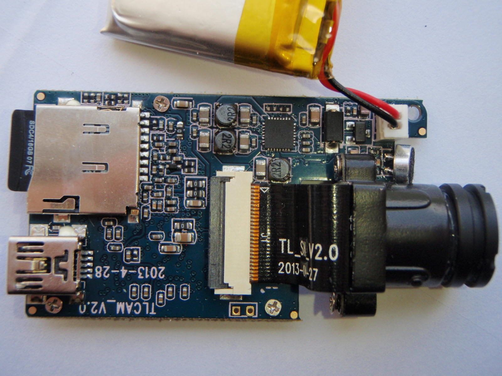  Lens The original lens, now being referred to as "Lens A" is a mid-AOV lens with some fisheye distortion in the 1080p frame size, but less than the wide angle D lens on the #16. When the camera is in 720p-60 fps mode the 1280 x 720 image is sub-sampled from the center of the wider 1920x1080 frame image, so the video horizontal field of view (HFOV) is proportionally less, but so is the fisheye distortion. In 720p-30fps mode, the camera keeps the wider HFOV of the 1080p mode, but scales the imaged down to 720p frame size (detail loss is very minimal). Vignetting and focus drop off at the edges are negligible. I measured the actual HFOV of the video frame width to be nominally 85 deg. at 1080p and 720p-30fps, and 46 deg. at 720p-60fps settings, and based on those, I estimate the AOV of the standard lens to be around 110 deg. The vertical FOV in 720p-30fps (or less) mode is nominally 54 deg. A wide angle lens, called Lens B, was later offered as an alternative, and more information on it can be found here. In Jan. 2015 a third wider angle lens, called Lens C, was released as a third lens option, and more information on it and how it compares with Lens B can be found here. Lens C quickly became user's preference over Lens B, which was phased out in the Spring of 2015. Then, inconsistent QC and low yield of acceptable high quality lenses force Lens C to be discontinued in July 2015, and it was replaced by Lens C2. More information on lens C2 and a comparison video with previous Lens C are available in this post. The CMOS module has a "standard" 12M x 0.5 thread, so it can accept other third party lenses if a user can find a suitable one. The CMOS imager and its ribbon cable attach to the lens module via two machine screws, making it possible to replace just the CMOS imager if necessary. Metal tape around the module and extending onto the rear metal CMOS attachment plate help to remove heat from the CMOS circuitry. This design was revised in May of 2015, with the metal backing plate for the CMOS imager changed to a circuit board with it's own cable connector. The new design eliminates a failure point of the ribbon cable, gives better alignment and support for the CMOS imager, and offers a 90 deg. rotation option for the CMOS imager, which gives the normal wide horizontal recorded image when the camera is rotated 90 degrees with the flat side vertical. More details on the new module are shown here. The original metal lens module was changed to a fiber reinforced composite version in Jan. 2015, but the design remains the same with a set screw to hold the threaded lens at the ideal focus point, yet allowing it to be released for focus adjustments if necessary. Approximate Weight of Basic Components Stock camera (inc. battery & memory card)..... 39 gms. (add 2 gms. for the wider angle lens) Case with heat sink...................................... 12 gms. Stock battery (520 mAh 603030)................... 10 gms. Optional battery (820 mAH).......................... 15 gms Circuit board, lens module, & memory card..... 17 gms. Mounting base plate without screw stud.......... 7 gms. Mounting base plate with screw stud.............. 10 gms. User Toggled Functions Camera functions are an expanded version of the #16 functions. The development of functions and user settings for the camera will be ongoing following the initial release, all of which will work in the camera when updated FW is loaded. The initial release FW includes: •Two user selectable video modes, toggled by the mode button after power up. Either mode can be set to record 1080p-30fps or 720p-60fps or 720p-30fps. The video format is .MOV with H.264 compression codec, and the camera can record sequential clips with a one sec. overlap, so there is no lost video. •Three movie quality settings (Super, Standard, and Low), which will vary the recording bit rates suitable for the user-selected frame size and frame rate. The Super setting (called the "High" setting in the GUI) with 1080p-30 fps video gives an approximate average total bit rate around 18,000 kbps with a high detail and motion scene. The Low setting with 720p-30 fps video gives approximately 5,800 kbps on the low end. •Five video recording cycle time settings will be 3, 5, 10, and 15 min. plus "Max", all of which will stop/save/continue. The Max setting will record until the 4GB files size limit is reached unless the memory card runs out of space or the battery power is removed. The actual Max recording time will vary dramatically accord to the users settings for frame size, frame rate, and movie quality. The 4GB file limit can be reached in less than 30 min. with 1080p-30 fps video set for Super quality. •Loop Recording will continue recording when the card fills up by deleting the oldest clip on the card to make room. This mode requires either a 3 or 5 min. clip length setting to work. Pressing the mode button while a recording is in progress in this mode will tag the file as write protected when it is saved, so it won't be overwritten. The file can be manually deleted, though. •Movie Flip (180 deg. rotation) will record a video right-side up when the camera must be mounted up-side down.Additional functions have been added with many FW updates since the initial release. The mSetup.exe configuration GUI program for Windows is the best resource to see all the functions available in the latest FW, though extracting the configuration file from the camera will also list them in brief text format along with the available configuration settings. Mounting Options The camera has many mounting options, starting with a flat base plate that slides onto the camera case's mid-line shallow groove.  Two studs on tabs that deflect as the camera is slid into place snap into holes in the camera case when it is fully inserted.  The camera is very solidly held in place on the base plate by the two lugs... maybe a bit too securely for some applications?  The lugs need to be lifted up by pushing on the rear of the camera case while holding the base plate into order to remove the camera.  The removal force can be greatly diminished to your preferences by shaving off a bit of the lug height as well as tapering the side of the lug to for a ramp. If you pursue this option, remove material in small increments and test the camera release force at every change.  The base plate can be mounted via wire ties or straps through slots in the bottom. The base plate also accepts a snug snap-in plug that has a standard 1/4-20 tripod thread.  Several heavy duty mounting options are available for mounting the camera to a variety of objects via the base plate tripod screw thread. Three of these are a flat surface adhesive pad mount, a bike handlebar mount (accommodates oversize bars), and a lever-actuated suction mount for smooth surfaces such as a car windshield. Each of these specific mounting options use an adjustable articulating ball piece that screws into the base plate, making very minute changes in alignment possible.  The optional helmet mount has both a slightly flexible adhesive pad plus a retaining strap for rugged use. The screw attachment point has only two rotation axes available for aiming the camera.  Another option is a mini-tripod bolt mount for use as a web cam or other use on any level surface. 
ImagesView all Images in thread
|
|
|
Last edited by Tom Frank; Mar 31, 2019 at 10:58 PM.
Reason: Added info on new lens C2
|


")
")


|
|
|
|
Thread OP
|
Firmware and Camera Configuration Settings
Camera Configuration and Firmware Information
It is strongly recommended that users with Windows PCs always use the mSetup graphical user interface (GUI) program to change camera settings and update firmware. This post has an overview of the Windows mSetup GUI software program authored by Isoprop. Download links for his mSetup program AND instruction manual (user guide) can be found here. This thread by Thomas discusses and has a link to his Android Mobius configuration application. This post has a link to a configuration setting tool for Mac PCs. New firmware and user settings can be loaded into the camera manually as a last resort (see below), but it requires specific file editing and handling procedures as well as multiple button press sequences on the camera. It is easy for user errors to cause these updates to fail! Also, there are numerous camera settings, some of which conflict with each other if both are toggled on at the same time. The GUI program will not permit these conflicting settings to be set so will eliminate all of these user error possibilities, so please do yourself a favor and use them. Optional Manual User Configuration Setting Procedure If a GUI tool is not available for your computer or you would rather just edit the configuration text file manually, it's easy to do, just follow these steps exactly: 1. Download the camera's configuration file to the flash card in the camera (HOLD DOWN MODE BUTTON, THEN ALSO HOLD DOWN POWER BUTTON UNTIL THE RED LED BLINKS 3 TIMES). 2. Turn the camera on, connect it to your PC, and access the camera root directory when it goes into the "removable disk mode". 3. Open the "SYSCFG.TXT" config text file with a simple (ASCII) text editor (e.g. the familiar "Notepad" text editor for Windows users). The file will look similar to this: Date time=[2013/06/28-21:33:34];date time setting,format yyyy/mm/dd hh:mm:ss Note: Values used by the camera shown bolded in the square brackets. Functions shown may vary with firmware updates, but manual editing is similar. Text in curly brackets at the bottom show the firmware and boot loader versions in the camera.4. Replace any number(s) in the square brackets with any valid alternate setting number, shown highlighted to the right of each function. For the date and time, don't delete the dash (-), slash (/), or colon (:) marks or add any spaces or invalid numbers. You can keep the camera's current date and time if you use a question mark (?) for each number, i.e. [????/??/??-??:??:??] will keep the camera's current date and time. NOTE: Except for certain functions which cannot co-exist, invalid numbers or other characters in the square brackets has not shown to cause serious problems. The camera appears to ignore them or switch to default values.5. Save the revised file back to the memory card root directory, but do not change the file name. 6. Upload the revised configuration back into the camera. The same key-press sequence used to download the configuration from the camera will also upload it to the camera. 7. When the LED turns off, you're done! The new configuration will be in the camera and the config file will be automatically deleted from the flash card. You may check the flash card to confirm this if you wish. Firmware Firmware updates will contain bug fixes, new or improved features, or both. You are advised to always update the firmware if you want your Mobius to give you all it can. You are strongly advise to ALWAYS use the GUI tool for all camera firmware changes (see above). The GUI will determine if your camera firmware is out of date, download the latest firmware if you agree, and install it for you, taking all the potential for user error out of it. The firmware development and refinment is a continuing process, and the most recent OFFICIALLY RELEASED versions will be kept attached to this post as downloadable zip files. Any problems found with the Released Firmware should be reported to me via PM. Note: The different firmware will ALWAYS have the same name... FWTLCAM.BIN, which is necessary for the camera to identify it as firmware to be installed. When you un-zip the attached firmware archive file, the firmware FILE will be in a named FOLDER so you can tell at a glance which firmware file is in the folder. When preparing to install the firmware as detailed below, make sure to copy the firmware FILE (FWTLCAM.BIN) and NOT THE FOLDER itself to the memory card root directory. The camera will not find the firmware if it's in a folder. I keep old, obsolete firmware in case anyone needs a copy (PM me with your email address). NOTE: BETA TEST firmware is created as part of the on-going development and is sometimes released to selected users for testing only. It is NOT officially released firmware and it may contain bugs, so is NOT intended for general distribution. . The Mobius only uses MOV format firmware. The most up-to-date firmware (and bootloader, if applicable) file is available for manual download at the bottom of this page. Optional Manual Firmware Update Procedure The following procedure is for manually updating your camera firmware. It is not necessary to do this if you can use the Windows GUI configuration tool (see above). It will determine if your camera firmware is out of date, download the latest firmware if you agree, and install it for you, taking all the potential for user error out of it. You are strongly advise to ALWAYS use the GUI tools for all camera firmware changes. ALERT:
2. Disconnect the camera and turn it off. 3. Insert the flash card containing the new firmware file into the camera (if not already in the camera). 4. Press the Power button until the BLUE LED turns on and begins to flash. RELEASE THE POWER BUTTON AS SOON AS LED FLASHING BEGINS! If you keep pressing it longer, you may turn off the camera before the update process is done. DO NOT PRESS ANY BUTTONS WHILE THE INSTALLATION IS IN PROGRESS (about 20 sec. to complete) 5. To confirm the firmware is being loaded into the camera, the BLUE LED will continue to blink during the upload process. 6. When the FW installation is complete, the BLUE LED will turn off for about 2 sec. and the YELLOW LED will then turn on solid, indicating the FW file is has been automatically deleted from the memory card. 7. You're done! The camera will be in the normal start-up standby mode ready for use. Firmware Download Site |
|
|
Last edited by Tom Frank; Jun 25, 2017 at 11:49 AM.
Reason: Added FW v2.41 for download
|
|
|
|
|
Thread OP
|
FREQUENTLY ASKED QUESTIONS (FAQs) - under construction
Camera Operation Problems
Camera Function Questions
BATTERY AND CMOS/LENS MAINTENANCE 1. Opening the case The case has a top and bottom piece held together by two screws on the bottom front corners and two interlocking tabs/lugs on the back. Remove the two screws, lift the front of the case slightly, and push it towards the back (away from the lens) to remove the bottom piece and expose the circuit board.   There are three tiny screws securing the circuit board to the case top, but you will never need to remove these for normal maintenance. 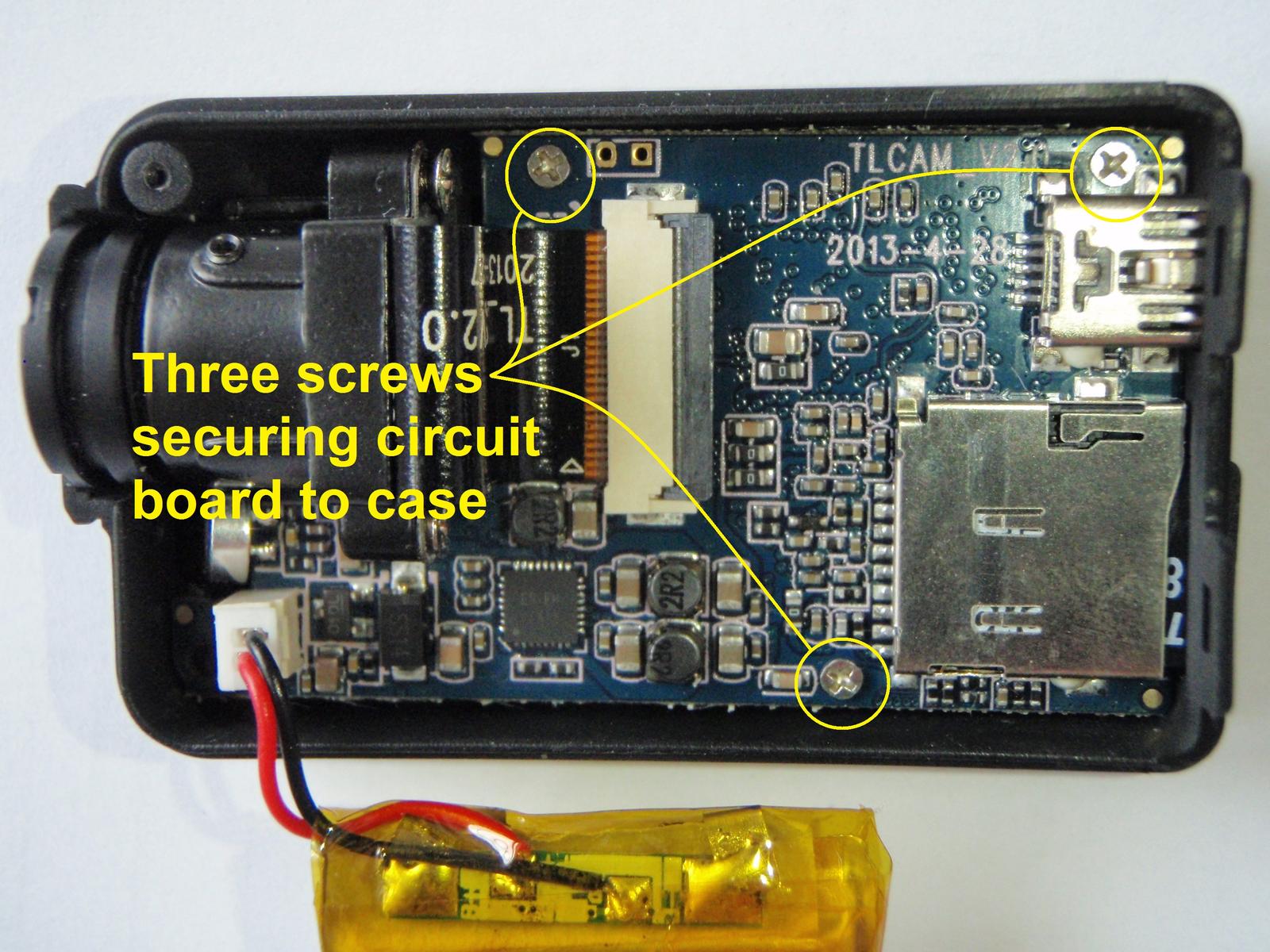 2. Replacing the battery The battery simply plugs into socket on the circuit board, and it has a key on the plug so it cannot be plugged in with wires reversed. The plug can be quite hard to remove, so a slight side-to-side rocking action with a thumb nail or NON-METALLIC tool in the gap between the plug and circuit board socket can help free it without exerting excessive force on the circuit board. Note the circuit board is long and narrow on that corner, and that portion is not secured to the case top when the bottom half is removed. Apply a little pressure with your thumb on the circuit board so it doesn't flex when removing the battery plug. NEVER PULL ON THE BATTERY WIRES to remove the plug! Plug in the new battery, re-position the cell and battery wires, and replace the case bottom when done. Note that the Mobius stock batteries have a small circuit board soldered to the battery tabs. This board has an IC chip that protects the cell from being over-charged or over-discharged. While this protection is redundant and a back-up to similar protection circuits in the camera itself, use of stock batteries is highly recommended to assure this added level of battery protection.  3. Replacing the CMOS imager module NOTE: The camera battery should be removed before doing this (see item 2., above)! The pictures referenced below incorrectly show the battery still connected! The CMOS module is press fit into a ribbed securement structure on the case. Because the CMOS ribbon cable is very short and can be damaged easily, it's advisable to first slide the ribbon cable from it's socket before the module is extracted. The ribbon cable slides into a socket on the circuit board and is clamped in place by a hinged clamping tab.  The cable is released for removal by gently lifting up on the aft edge of the clamping tab with a thumb nail or NON-METALLIC tool, such as a toothpick. 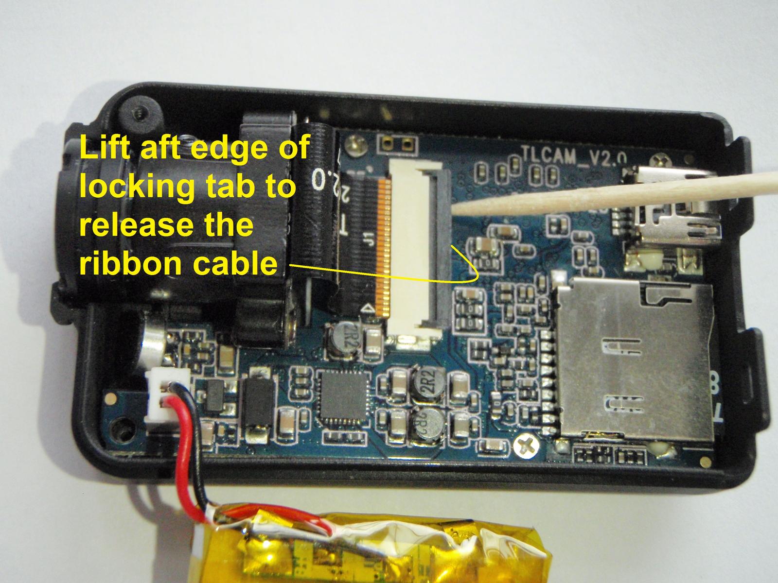 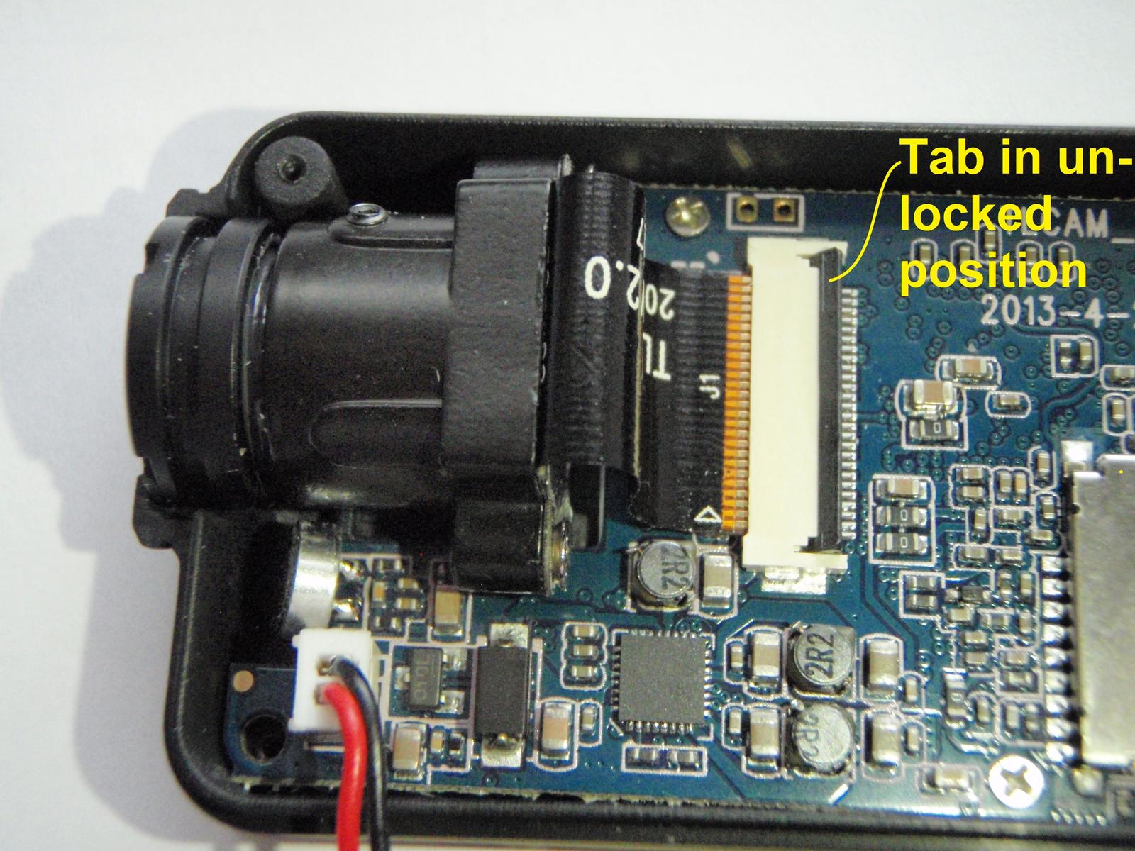 Gently slide the ribbon cable out of the socket with a NON-METALLIC tool such as a toothpick.  Now the CMOS module can be extracted from the case, but it is a very tight fit and should be done carefully. I find the best method is to use a tool as a lever to just slightly lift one side of the module at the screw lug A strong (e.g. metallic) tool may be needed for this, and can be used without getting close to any circuitry if applied at the side of the module near the edge of the case. Once the edge of the module is lifted, the module can be easily removed with your fingers. Just be careful to not grab the ribbon cable.   Replacing a module is slightly different. First, if your lens module has some metallic tape on the underside, do not remove this tape because it's purpose is to conduct heat from the metal CMOS back plate to the metal module housing which then helps cool the CMOS imager. But do look to be sure the tape is aligned on the module and does not have any creases or folds that can keep the module from seating fully in the case.  Next, with the locking tab lifted, gently insert the ribbon cable into the circuit board connector, making sure it is fully inserted. Use a wooden toothpick or other tool to help position and push the push the ribbon cable into the socket. It's a snug fit and needs to be inserted straight with maybe a slight side-to-side rocking motion. DO NOT force it. When in place, close the locking tab to secure the ribbon.  Now position the module over it's seat in the case, allowing the ribbon cable to bend naturally. DO NOT force a sharp bend in it. When in place, push the module into the case slot by pressing on the side lugs. DO NOT press on the ribbon cable area on top of the module. It's a very snug fit, and a slight rocking side-to-side rocking motion may be needed. Make sure the lens is centered in the case opening and replace the case bottom.  4. Refocusing or Replacing the Lens in the CMOS module Refocusing is easier if your module has the set screw to prevent the lens from rotating rather than glue. The lens is loosened by backing out the set screw with a 1mm (I think) Allen hex wrench.  NOTE: If your images are out of focus on one side and in focus on the opposite side, it's either due to the lens being cross-threaded OR the CMOS chip in the module is not mounted perfectly flat and perpendicular to the lens optical axis. You can fix the former if you completely remove the lens barrel from it's module, and re-installing it while holding it exactly perpendicular to the front of the mount. You can fix the latter by inserting a very thin shim(e.g. like a strip of paper, electrical tape, etc. under the side of the metal CMOS plate where the out of focus side is. Just loosen the screw on the back of the module just enough to slip the shim in between the metal plate and the plastic module, then retighten the screw. It's necessary to determine which side of the module needs the shim, however. You can do that by trial and error, or by loosening the lens securement set screw and turning the lens clockwise slightly (e.g. 5-10 deg.) and observing whether the out of focus side get better or worse. If it gets worse, put the shim on the side that was out of focus. If it gets better, put the shim on the opposite side. Then refocus the lens to see if the entire frame can be brought into focus (see procedure below). If it can't, you need to modify the thickness of the shim accordingly. Also see this post for another procedure. Also, some wide angle lenses have a slightly curved focal plane, so getting the image in perfect focus at the center and at the extreme corners may not be possible. Finding the best overall focus for the entire frame will be a compromise. The lens is focused by turning it in it's plastic base module. Screwing the lens clockwise (looking into the front of the lens) moves it deeper into the module and moves the image focus further away from the lens, and conversely, rotating counter-clockwise moves the lens further out of the module and brings the focus closer to the camera. Some lenses turn easier than others, so do these steps first: 1. Open the case (see instructions for tips), unplug the battery, and inspect the lens threads all the way around for any evidence of glue. If you need to remove the circuit board, remove the three very tiny screws along the edges and carefully lift the circuit board from the case by it's edges (DON"T LOSE THE SCREWS!). Be careful not to pull on the ribbon cable that connects the camera to the circuit board. 2. Mark the initial position of the lens with a narrow line of paint across the threads AND onto its square plastic base. If there is any glue visible at the junction of the threads and the module, you'll likely need to remove it to get the lens to turn freely. The glue can often be removed by picking it out of the thread with a very pointed and sharp hobby knife blade. The glue may need to be softened for removal or to get it to release. I've found CA glue dissolver to be very good for this, but use it VERY SPARINGLY! Apply a very tiny amount on a pointed toothpick and use it to dab a tiny amount around the junction of the threaded lens barrel with the module and let it wick around into the threads. I use a pointed toothpick wetted with the dissolver to apply it in tiny amounts. Once the lens starts to turn, remove any residual liquid from the threads with a tissue forced into the thread roots with a sharp hobby knife. If the module has the set screw, loosen it a turn or so, but be careful that it does not come completely out. It is very tiny and easily lost if it falls out. If the lens appears to "jam" and not unscrew easily, see this post for a possible reason and solution. 3. Hold the CMOS module very securely and SLOWLY try to turn the lens, making sure not to put any pressure on the ribbon cable which has fragile copper traces embedded in it. If you crack a trace the module will be ruined. Better yet, remove the ribbon cable from the module if your camera has the later design that has a ribbon clamping socket on the back of the module. Be careful and don't use excessive force... the parts are plastic so they can break if you get too aggressive! 4. Assuming you have been successful, you'll need to determine which way to rotate the lens for better focus, and there are three methods for that: The WebCam Method
This method relies on the premise that the size of a still image file will increase in size the better the image is focused (i.e. the sharper detail requires more file information to define it, so the file must be larger.
The Video Trial/Error Method This method is good if you have a hard time determining best focus via the other two methods. It can be more time consuming, but is easier to see and compare lens positions with one another for best focus.
To completely replace the lens, you may need to remove the module from the case depending on which lens is in the camera. |
|
|
Last edited by Tom Frank; Dec 24, 2022 at 06:44 PM.
Reason: Added additional info in the lens refocusing section
|


|
|
|
|
Thread OP
|
Video Samples and Editing Tips
Video Samples
1. An excellent review of the Mobius camera by "Techmoan" can be viewed here, with excellent video samples that can be download here in their native quality direct from the camera. 2. Sample side-by-side video comparison outdoors in very low light with wide dynamic range (WDR) on and off. Editing Issues The Mobius video files are similar to those of it's predecessor, the #16 720p HD keychain camera. Though the higher resolution and data rate of the Mobius files will demand more from your PC hardware and resources, this post from the #16 support thread gives useful editing issues and solutions for those who are new to video editing and want simple (and free!) software to get started. |
|
|
Last edited by Tom Frank; Jul 06, 2014 at 09:09 AM.
Reason: Added Editing Section
|
|
|
|
|
|
mSetup - the Mobius ActionCam setup utility and User Guide
This is the original Mobius GUI which I created in co-operation with the developer and Tom. Click HERE to download.
The program is a native Windows application specifically written for the Windows operating system (XP and above) and does not require any 3rd party runtime system, for example Java or .NET, to be installed. The simple and extremely user-friendly program is fully plug-and-play and includes an integrated User Manual. The software is also compatible with all plug-and-play versions of the Mobius' little sister, the very popular #16. The software will also identify all unknown USB cameras and devices with a capacity of 64GB or less. So, if the GUI doesn't recognize your camera, you don't have a #16 or a Mobius ActionCam! You can take a peek at the software even if you don't yet have the camera. You can click on all the buttons, but they will be greyed-out until a supported camera is connected. The integrated help may also be useful. Remember that you can resize the dialog by dragging the gripper at the bottom right corner if you prefer a smaller image. The dialog fonts will automatically be resized to fit. The latest GUI software configuration tool together with the latest instruction manual (User Guide) may be downloaded by clicking on the link above or on one of the images below. I strongly recommend that you enable automatic program and firmware updates so you always benefit from the latest available tools. This is specially worthwhile during the first few weeks after the initial release. Here are some screenshots of the GUI (Graphical User Interface) 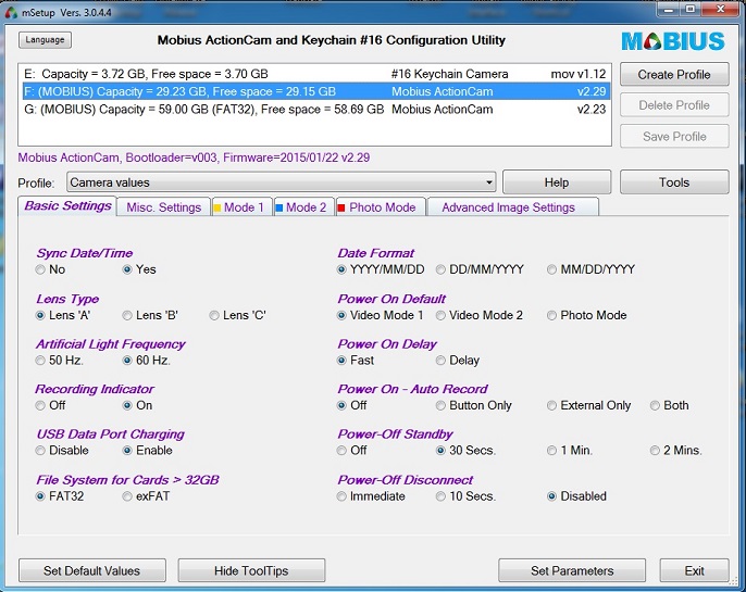 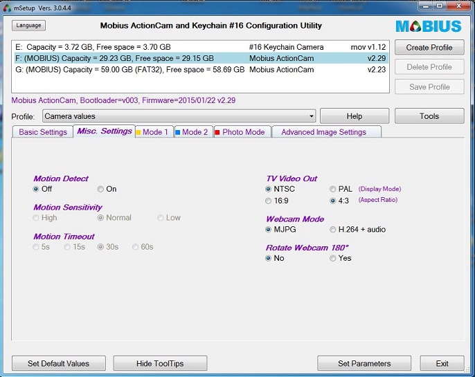 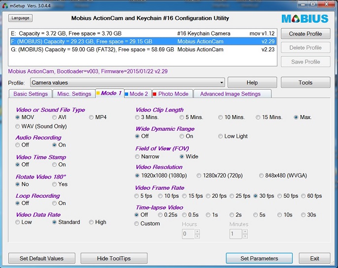 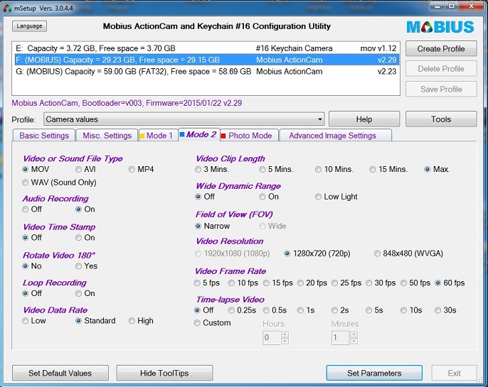 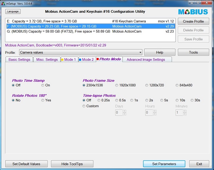 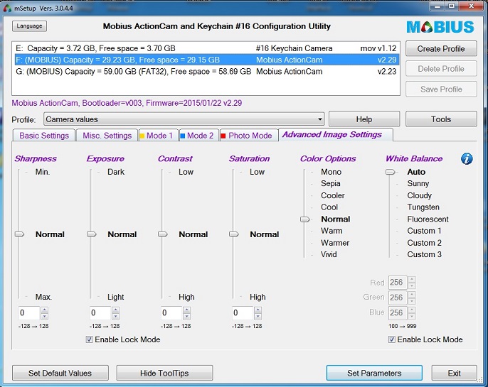 ... you can set your own parameters and download new versions and format the camera's card 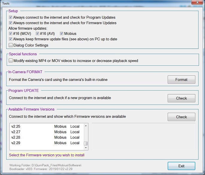 ...and of course you can set your own colors for the program 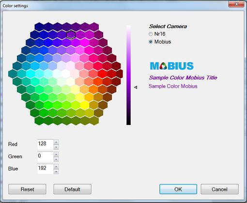 ... There's also a function where you can increase or decrease the playback speed of any .mov or .mp4 media files 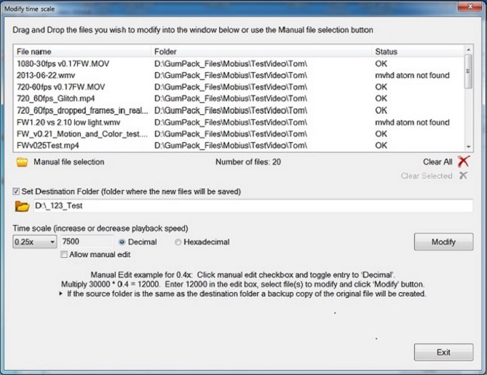 ...and lots of useful information too 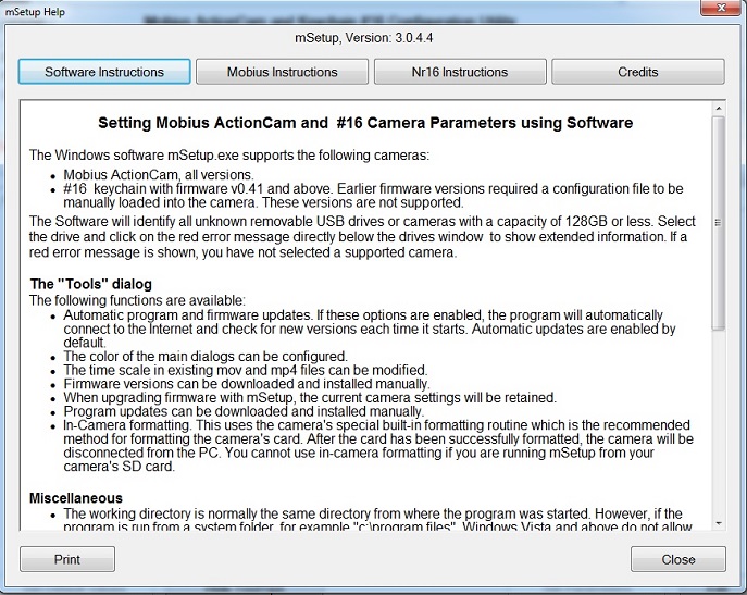
|
|
|
Last edited by Isoprop; Mar 18, 2019 at 08:37 AM.
Reason: Screenshots not shown correctly
|
|
|
|
|
|
The definite Guide to Power connectors, charging, and other power related questions
Mobius ActionCam
This guide is designed as a reference for the most common power-related questions and is thus fairly long. However, I hope you will find the answer to your question. This post will be kept up to date. Description The Mobius ActionCam will run for about 80 minutes from a new fully charged 520mAh internal battery or for over 2 hours with the new 820mAh internal battery. Recording in cold weather will drastically reduce the recording time. Since you can't physically turn the battery off, the battery will always drain in order to keep the clock running. I don't know how long it will take to completely drain the battery, but I would expect a year, most probably much longer. The camera can be configured either manually by editing an ASCII text file or much more conveniently by using the mSetup program (see post #6). Recording without sound will give slightly longer recording times. Likewise, recording with a low video data rate will slightly increase the recording times. The recording indicator (flashing LED while recording) has no noticeable effect on the recording times. The recording indicator can be turned on or off in the configuration utility / text file. The camera always records "clips" of a given length. The clip lengths can be set in the configuration utility / text file (see above). If the "Max." value is set, the camera will record clips with a length of 4GB. After the camera has written a clip, it will automatically create and record a new clip. This procedure will be repeated until the battery reaches a given threshold (runs out of power) or the flash card is full. If the camera is configured for loop recording, the oldest clips will be overwritten and recording will continue until there is no more internal or external power. There will be a 1 second overlap of two consecutive clips. The camera supports SD/SDXC cards formatted in FAT32 or exFAT and supports cards up to a max. of 128GB. Larger cards will not work. Internal battery The internal battery is a lithium polymer cell (LIPO), which, when fully charged, has a capacity of 4.2V. The camera will turn off when the battery voltage reaches approx. 3.5V. The battery is user replaceable and comes with a tiny 2-pin connector. Since a connected external USB power supply will always supply more power than the camera functions require, the internal LIPO will be charged even when using the camera in Disk Mode, Webcam Mode, or Recording. Battery protection circuitry is built into the camera. For this reason you should not replace the internal battery with another type of battery (for example Li-Ion). It is, however, possible to connect an external LIPO 1S battery in place of the internal battery but it should be recharged using an external charger. The built-in charger circuitry is designed to charge a 520mAh LiPo (603030). Newer cameras are designed to use an 820mAh LiPo (803132). Newer models are date-stamped with 2014-08-19 (or later) on the circuit board under the lens module cable. A depleted battery will take between 2 and 2.5 hours to fully charge with the camera turned off. The green LED will be extinguished when the battery is fully charged. It is safe to assume the battery is fully charged after 2.5 hours even if the green LED is still lit. The latest 820mAh batteries will fit into older cameras but will take much longer to fully charge. You should never connect a second battery in series. Doing so will destroy your camera because the voltage is the sum of all the battery volts. You should also not connect batteries in parallel unless they have been properly "balanced" by an external charger. If the cells are not at the same state of charge, the higher charged cell(s) will try to charge the lower charged cell(s) with no current limit. This could damage the cells and cause dangerous overheating of cells and wiring. If you replace the internal battery with another source of power (battery, charger, etc.) the supplied voltage must not exceed 4.2V (5V is not permitted on the battery connector). Doing so may initially work but will over-stress other components and will most likely lead to premature camera failure. If you must connect a 5V supply to the battery connector, then use a small diode (e.g. 1N4001) wired in series in the positive line. This will drop the voltage by about 0.7V. You obviously have to connect the diode correctly or no current will flow! Using an external single cell LIPO in place of the internal battery Some users my prefer to use a larger single cell LIPO in place of the standard one. This is possible so long the internal battery is never connected at the same time. You should note, however, that charging a larger battery using the Mobius' charging circuitry will take a very long time. Also remember that every time you disconnect the battery from the board, even very, very briefly, the internal clock will be reset. The USB cable A standard mini USB cable has +5V connected to pin #1 of the camera's USB socket and -V (ground / earth) connected to pin #5 of the camera's mini USB socket. On a standard mini USB plug the two center wires (Pin #2 and Pin #3) are the data lines and are only used when the camera is connected to a computer. They are not used when the camera is connected to an external power source such as car battery charger, external wall charger (mains charger), external USB power pack etc. The camera "tests" the data lines as well as pin #4 to determine the connection type. The camera can be operated normally using external USB power with the internal battery disconnected. Pin #4, which is sometimes called Pin x, will switch the camera into AV-out mode (TV-Out) when connected to ground. When in AV-out mode, pin #2 carries the composite video-out signal. In addition, pin #3 carries the audio-out signal when the camera is in playback mode. When switched into AV-out mode by connecting pin #4 to ground (see above), there will be a composite video signal present on pin #2 as soon as the camera is turned on. Auto-power-off will automatically be disabled. A word of caution for #11 owners: If you use the #11 "special" cable on your Mobius ActionCam you will destroy it! The table below shows all the possible cable connections. In practice you will only need max. 2 different cables. The Mobius is normally sold with a universal cable harness. 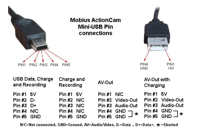 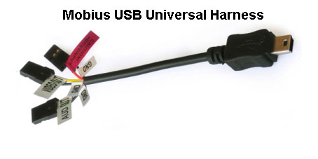 Charging only, using a standard USB charger When charging, the green LED will be on. When fully charged, the green LED will be off. The camera can be charged by any standard *USB source. This includes: • USB mains adapters (wall adapters), e.g. mobile phone chargers, navigation chargers, USB chargers, etc. • USB standard car battery chargers. • USB backup batteries designed to power/charge mobile phones, navigation devices, etc. • USB computer connection. ►Only use quality chargers capable of supplying 1000mA (1A) and a stable voltage of at least 5V. Low quality chargers may not be able to supply enough current and can lead to premature battery failure or, in the worst case, even destroy the camera. * Not all USB devices can supply enough current to charge the internal battery. Most mobile phones etc. will NOT be able to charge the battery. Charging only, using a PC When connected to a PC with an SD card inserted, the camera will be connected as an external drive. The battery will be charged. If you only want to charge the battery, briefly press the Power button to turn the camera off. It is advisable to "safely disconnect" the drive before doing this (method varies depending on your operating system). Simultaneous Charging and Recording using standard USB cables/adapters The cable can be connected to any USB power source as long as the power source can supply 5 Volts under load. Note: Some USB hubs do not supply enough current. If the USB hub can't supply a nominal voltage under load, the camera will run on the internal battery which will be flat before the battery has a chance to charge! • When powering from the computer, the recording must be started before connecting the USB. • When powering from an external USB power source, the cable can be connected at any time, e.g. when the camera is turned off, before starting the recording, during the recording. ►Only use quality chargers capable of supplying 1000mA (1A) and a stable voltage of at least 5V. Low quality chargers may not be able to supply enough current and can lead to premature battery failure or, in the worst case, even destroy the camera. ►The battery or charger must only use the +5V and Ground wires. Some batteries/chargers also use the data wires. In this case the camera will think the power source is a computer - i.e. you will never be able to record more than one clip! Cut the two data wires (usually white and blue or green) and the battery/charger will work as expected. Using external power it is possible to record about 4.5 hours of continuous video (many clips created automatically) using a 32GB micro SD card or about 8.5 hours using a 64GB micro SDXC card or about 17 hours using a 128GB micro SDXC card. These are average values using standard settings with 1080p30. I highly recommend the Just Mobile Gum Pro PP-08, but any other USB high power external battery power packs will also work. Technical • When the camera is turned off, the RTC and processor draw about 15μA. • When the camera is turned on, but in standby mode, the camera consumes about 300mA. • When the camera is recording, the camera draws between 350mA and 400mA. • In order to protect the battery, the camera will stop recording and turn off when the voltage falls below approx. 3.5V. Haku made the following measurements in post #1502: No battery connected • Standby mode: 225mA @ 4.97v • Standby mode with AV-Out enabled: 265mA @ 4.97v • Recording 1080p: 305mA @ 4.97v • Recording 1080p with AV-OUT enabled: 330mA @ 4.96v Battery connected • Battery being charged from flat, powered off: 186mA @ 4.97v • Battery being charged from flat, recording 1080p: average 505mA @ 4.95v Using the camera with only external USB power (internal battery disconnected) The camera can be used without a battery connected to the internal connector on the board. Remember that the RTC (Real Time Clock) will be reset every time the external USB power is removed. • The camera requires an absolute minimum of 4.18V to operate correctly. This value may vary with the type of card used. I would think 4.3V would be a safer figure. • It is possible to use a supercapacitor in place of the internal battery. This will keep the RTC running for up to 10 days. It is not possible to use the supercapacitor to power the camera. Installing a supercapacitor requires the camera to be powered by external USB power. A word of WARNING External power should be a nominal 5V. Fractionally higher voltages (such as from a fully charged 4 cell NiMH battery pack) can be tolerated without undue stress of the camera components • The latest cameras (2014-08-19 or later) incorporate over-voltage protection and should protect the camera against excessive voltage up to 28V max. If the voltage exceeds 5V the battery will not charge. Reverse polarity or connecting incorrect USB pins will damage the board. RC electric plane models - Warning It is not recommended to plug the camera into a spare channel on the receiver. This may work, but it may also cause complete shutdown of the external electronics. If the voltage supplied to the camera's USB port is in excess of 5V (�5%) there is also the risk of over stressing the camera's circuitry. When recording, the camera draws as much power as a mini servo... and a bit higher when also outputting composite video for FPV. If the receiver is being powered by a separate battery, then the solution may work as long as the battery can handle the extra current. If the receiver is being powered by a linear BEC circuit on the motor ESC, adding the camera to that circuit may overload it and cause it to go into thermal shutdown, which in that case would mean total loss of control and a crash scenario! If you must use a spare channel on the receiver, the complete electrical circuit needs to be taken into account and no components should become warmer than usual. External USB battery packs You cannot use a battery box with only 3 AAA / 3 AA batteries unless it incorporates step-up electronics to output 5V. 3 Batteries can only supply about 3.6V, but the camera requires a minimum of approx. 4.7V constant voltage. It will not charge or record when the voltage falls below approx. 4.3V. Commercial external USB battery powered chargers There are many different external USB battery power packs available. Mobius sellers may also stock them. A word of warning. Some 'Intelligent' power packs have recently appeared on the market that shut down when the current draw drops below 50mA! Don't use these chargers - they will most likely not work correctly and may even cause damage to your camera. A power pack that automatically turns off defeats the whole idea of using external power! The most reliable battery packs are those which don't need any cable adapters. A few examples follow. This is a typical external USB battery pack which can be found on eBay for about $30. It has enough power for the camera to record video to almost completely fill a 32GB card. 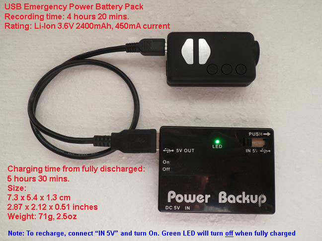 This one is expensive, but by far the best. Costs more than $45. Can also be found on eBay. A real power horse! Note: The cable supplied will NOT work for charging and recording at the same time. You must make your own 2-wire USB cable or simply cut the two data wires. 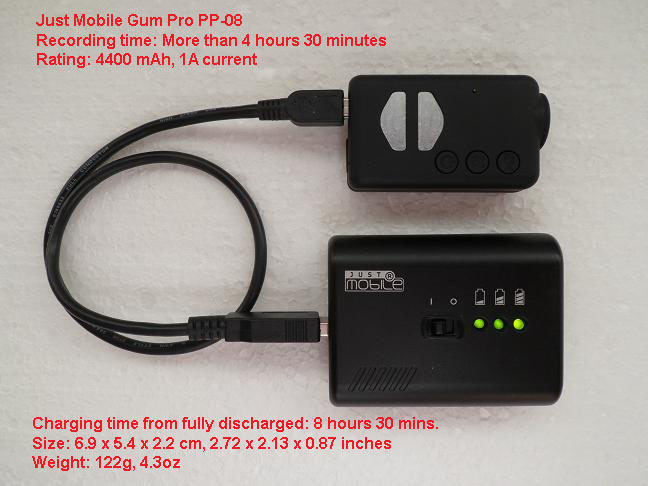 Car Charger (optional) The optional car charger converts 12V DC into 5V DC. The center pin is the +5V and one of the connectors on the side is Ground (Earth). Any standard USB cable can be used together with the car charger. If the car charger electronics are used with or without the casing to power the camera from a different 12V power source (external 3S lipo packs, for example), then the circuit will work well, but is probably too large to be practical. Any 12V - 15V DC sources which need to be converted to 5V must go thru the car charger electronics (or similar regulator). You must NEVER bypass these electronics or apply 12V directly to the camera - doing so will destroy the camera. 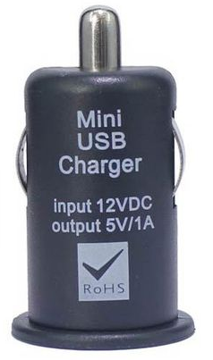 DIY 3S LiPo Voltage Converter bouzx6r has posted a simple method of converting a cheap car battery charger (see above picture) into a 3S LiPo-to-5V voltage converter. His idea may not be as small and compact as commercially available devices, but it's most probably just as good or even better. Click here for the original link with pictures. |
|
|
Last edited by Isoprop; Mar 18, 2019 at 08:36 AM.
Reason: Keeping post up-to-date
|
|
|
|
|
|
Android appsAndroid apps are listed below: OTG Status This app tells you if your phone/tablet provides basic, limited, or full USB OTG support. It also tells you if your phone/tablet can run the apps listed below; if not, it tells you exactly why. Mobius ActionCam / #16 Camera: Mobius USB Tools is simply THE best, most sophisticated, and most advanced Android app for all cameras (past, present, and future) developed by Elijah Xie. Providing super smooth User interface for configuration and HD LiveView, Mobius USB Tools automatically matches camera mode without any User intervention. See list of all app features. UVC compliant USB cameras: USBcam is a generic WebCam app for most UVC compliant USB cameras using the MJPEG video format: ActionCams, KeyCams, WebCams, USB Microscopes, USB Telescopes, etc. Available videos: See Play Store for available app names and their descriptions. |
|
|
Last edited by therau2000; Nov 26, 2016 at 06:24 AM.
Reason: Updated info
|
|
|
|
|
|
Camera extension cable
Do you sell an extension cable for the camera?
|
|
|
|
|
|
|
|
|
It is possible to subscribe to a thread without actually having to post, at the top of the thread click on the thread tools button and select subscribe. I expect Tom will come through and delete a few of these posts as they really serve no purpose to the subject (including this post).
|
|
|
|
|
|
||
|
|
You'll need to give the sellers a bit of time to set up their sites! The Mobius is available NOW.
The two official sellers in China are listed in post #2 but they don't yet list the Mobius. If you're really in a hurry, email them for an offer. JooVuu should also have these cameras in stock but are not yet officially listed in post #2. JooVuu is based in the UK. There are no extension cables available yet. Before you ask, No, you can't use the extension cables designed for the #16. The Mobius extension cable would have to be two wires wider than the cables used in all the 720p keychains. Quote:

|
|
|
|
||
«
Previous Thread
|
Next Thread
»
| Thread Tools | |


| Similar Threads | |||||
| Category | Thread | Thread Starter | Forum | Replies | Last Post |
| Discussion | Heli Pad Review Series: SYMA X3 Quadcopter Review | Heli Pad | Mini Multirotor Drones | 121 | May 28, 2015 03:30 AM |
| Discussion | Olypic II is under construction now | Texas Buzzard | Sailplane Talk | 16 | Aug 10, 2014 12:54 PM |
| Video | Quad filming roller coaster under construction | Brian_ | Multirotor Drone Talk | 1 | Mar 04, 2013 02:19 PM |
| Todd's Tiny under construction | Tres Wright | Parkflyers | 30 | Jun 23, 2002 11:20 PM | |