|
|
|
|
Thread OP
|
Build Log
My first adventure in flight... what starts as a tricopter becomes a v-tail
I have been into the RC thing for a long time... but always ground based. Some nitro monster trucks, some buggies... my last toy was a RC Crawler, but a buddy of mine got into helicopters and after seeing a few Quad's and such I was sold. After weeks of reading and researching, I have decided on doing a Tricopter. My first thought was to build a Quad, but that is just too simple and they all end up looking like large flying blocks.
I think a tricopter will fly with more style, and should end up being alittle cheaper since I am not buying 4 Motor's and ESC's, only 3. I watched a few video's and realized building a Tricopter frame wouldnt be any easier. The rear Yaw pivot seemed to add a challenge, but I knew i had the parts needed to do it. So I went digging through a couple boxes of spare RC parts, and came up with something that should do the trick. Here is my first setup:  Its from an old buggy frame, a rear axle hub rotated on its side. I figure I should benefit from the double ball bearing setup. Here's some quick video of its basic operation... https://picasaweb.google.com/lh/phot...eat=directlink After jumping that hurdle, it was off to Home Depot to get some Aluminum square for my frame. I opted for 3/4" square tube, and picked up some 90 degree aluminum stock as well for various brackets and such. For the body I got 2mm lexan. It only took a few minutes to cut the arms to length, and fit my rear yaw mechanism.   I used the other steering arm, and cut the horn off, and trimmed the hub with a dremel to make it fit snug into the hollow aluminum. I then marked where some of the original holes lined up, and ran screws through both sides to secure the assembly inside the frame. Also at the bottom I drilled a 3rd hole and placed a 2.5mm screw in place as an extra precaution. Video of the assembly in operation can be viewed here: https://picasaweb.google.com/lh/phot...eat=directlink For the body I used RCexplorers .pdf but just made straight edges instead of curves. This would be my first attempt at cutting with my new saw, and I didnt want to try anything fancy. I increased the size by 30% to compensate for my larger arms.   At first I wanted to use rivets to hold the body plates to the arms. But after securing the tail, and then each wing, I realized it would be best to just use 4mm bolts and run them through the entire assembly. So I drilled out the rivets and am now at a stand-still, waiting for some parts to come in that I have ordered. Which brings me to the good stuff!! the internals. This is what my HK order consists of: KK2 Flight Controller - https://www.hobbyking.com/hobbyking/s...dProduct=24723 DT750 Motors - https://www.hobbyking.com/hobbyking/s...idProduct=6247 Turnigy Plush 30A ESC's - https://www.hobbyking.com/hobbyking/s...idProduct=2164 10x4.7 Propellors - https://www.hobbyking.com/hobbyking/s...dProduct=20864 HobbyKing 939MG Servo - https://www.hobbyking.com/hobbyking/s...dProduct=14458 And also a few other goodies like the Programming card for the ESC's, low voltage alarm, 2200mah 20c 3s lipo's (two) and a USB connector so I can use my Turnigy 9X in Realflight and crash on the PC instead of real life! So yeah... I guess this is the first step. The next step is to wait for my parts to come in so I can setup the KK2 position along with my RX and battery etc. |
|
|
Last edited by AcroFPV; Oct 30, 2012 at 12:16 AM.
|
|
|
|
|
|
|
Thread OP
|
So as I wait for my parts to arive, I thought I would continue to progress on the rear yaw design. Now that I have the movement down, i need a way to secure the motor. I found some spare plastic that I shaped, and used as a spacer to offset the uneven steering knuckle. Then cut some spare Plexan that I used for the body, and used Gorilla Glue to hold it all together. Once the glue had cured, I then used a drill bit and drilled some holes through the entire assembly on each side of the axle it pivots on. Once the holes were drilled, I used a couple aluminum sleeves I had from some unknown RC setup, and pressed them into the Lexan, so my screws do not wallow through the plastic and oval my holes.
  Afterwards I used some allen head screws and locknuts and ran them through the entire assembly and bolted it solid. I had to dremel the underside to fit the locknuts evenly, but in the end everything came out exactly as I planned.   The entire assembly is very solid, and there is no free play at all. The shaft that the rear motor pivots on, is supported by 4 ball bearings. Two in the motor mount, and 2 in the frame. The only slop is in the connecting rod between the mount & servo. I took a couple video's of it in action: https://picasaweb.google.com/lh/phot...eat=directlink & https://picasaweb.google.com/lh/phot...eat=directlink I ordered 4x30mm bolts, and locknuts with washers for my frame, and as soon as those show up I can re-drill the body plates & find places to secure everything. The next step is to come up with some vibration dampening mounts for the KK2 board. I have some fuel line and PC Motherboard spacers to play with and try to come up with something 
|
|
|
|
|
|
|
|
Thread OP
|
So I found some time today to work on the frame. I drilled out all the rivets and expanded the holes to fit the 4m bolts. 30mm long was just long enough to fit the two washers. After doing the pivot bolts for the right & left arm, I realized as tight as I have those nuts and bolts, there's no way its going to easily fold. So I drilled some new holes and just hard-mounted the arms. I have alot of room in the back of my truck, so the frame doesn't need to be ultra compact. Besides, the frame is still small enough to fit in the truck of my wifes Hybrid if it needed too
 So with that said, here come the pictures!!  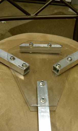   It feels real stable and light. Its as solid as a rock, which worries me... in case of impact im not sure what is going to bend or break? I think while i wait on Hobby King, I will continue and work on some landing gear. I have a few idea's floating around in my head, and am thinking of bending some metal coat hanger for most of it. Also I found something I might use as my canopy    Its from my Losi Mini Crawler. I trimmed it some, i might trim it more. I am thinking of cutting the rear portion off, and leaving just the hood & cab. I am going to wait till I have a FC mount setup before I worry about that though. |
|
|
|
|
|
|
|
Thread OP
|
Today I broke down the frame and drew out some guidelines. I have two RX to chose from, a 6ch and a 8ch. Both will fit easily between the arms inside the body. I marked where I will have to drill some decent sized holes to fit all my wiring through. My plan is to paint the top body plate, and leave the bottom body plate clear.
 I was also brainstorming and I think im going to trim the ends of each left & right arm. Put a bevel on the bottom of the motor mount so it doesnt just have a square end. The idea would be to cut away the black area... 
|
|
|
Last edited by AcroFPV; Aug 06, 2012 at 10:21 PM.
|
|
|
|
|
Thread OP
|
FINALLY Hobby King has shipped my order!! So only about a week left to wait.
So I haven't really got ALOT done. Other than dropping my Frame and breaking the Servo from the frame. Oh well, I have a replacement Servo on my HK order. And we'll chock that up to a bench test, and found a flaw in my Servo Mount I also trimmed my Body alittle more, and I trimmed the left & right arms and gave them a bevel.    So I guess I play the waiting game. I think my next step is to get some wire and solder up a wiring harness in preparation for the rest of the gear... |
|
|
|
|
|
|
|
|
looking good so far, what AUW are you shooting for? Btw did you get the lexan at Home Depot?
|
|
|
Last edited by TheKnightFerrin; Aug 13, 2012 at 11:44 AM.
|
|
|
|
|
Thread OP
|
I'm just going to put this here cause Im not interested in finding the right sub-forum or where-ever it would be most appropriate. But its alittle off-topic from the tricopter build, however related.
I need a 12v DC power supply for the charger I ordered. And i have been reading about converting ATX PC Power supplies. It just so happens i had a stack of old power supplies in the garage, so I found one (and only 1 of the 3) that would power up, and went and hacked it... adding a switch, and removing every wire exept; x4 Black Ground x2 Yellow +12v x2 Red +5v and the green wire ran to a switch, to power the supply on & off. The other 2 dead power supplies did not goto waste, as I salvaged their 12v brushless cooling fans, and wired them together Now with all this complete, I needed something to put it all in, so I cleared out an extra metal toolbox I had collecting dust, and got to work...  The original idea was to store batteries, the supply, charger and some extra tools & hardware, however after looking at all the spare room, I decided to fit my Turnigy 9X transmitter instead  I cut the original styrofoam insert that the 9X came with, and hot-glued some spare piece that I cut away, and it holds the transmitter very firmly and should protect it from any harm.    There is still plenty of un-used room in the lid of the toolbox. I will most likely create a storage for batteries, and mount the charger up there. Still not 100% sure how the layout will go, might have to wait for the charger & batteries to arive to finish things. |
|
|
|
|
|
|
|
|
Interesting project. I like the car body. Ive often thought about making a simple quadcopter with a lexan lamborghini countach or 57 chevy 1:10 body.
|
|
|
|
|
|
|
|
Thread OP
|
ALRIGHTY!!! My hobby king order came in! I was waiting at the door for the mail man, like a dog waiting for his owner.... panting and drooling from the my mouth. I couldn't even sign my name on the reciept I was so excited!!
I quickly unwrapped everything and laid it out to make sure nothing was damaged. Everything appears to be in a single piece, and accounted for... 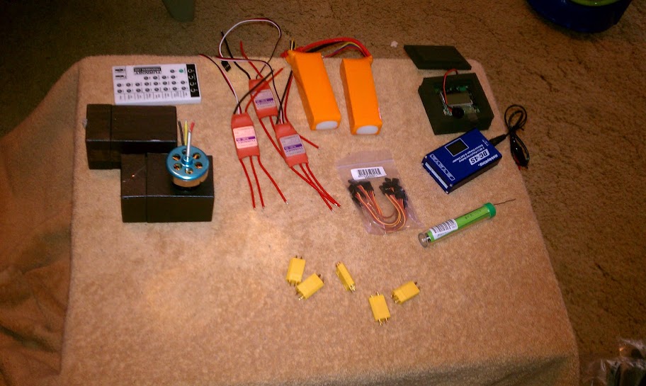 I guess even after reading thread after thread about the DT750 and how big it is, i was struck by the size of them. But they should do well. I spent a couple hours here and there in the garage and managed to get some work done. First thing was to replace the bullet connectors on the batteries with the XT60 connectors. Then I charged both batteries and started soldering together my motors and ESC's...  I also added some clear epoxy to the wires on the DT750 as a precaution. 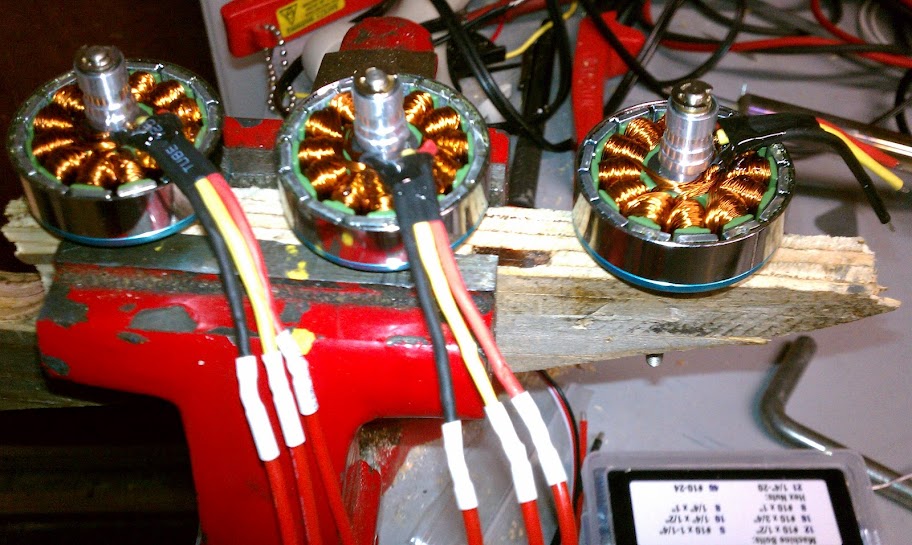 One last order of business before I turned in for the night, I wanted to see if I could come up with solution for the motor mounts. It appears some more design will be needed for the left & right arms, but my Yaw was pretty much perfect size for a motor mount. I centered one of the mounts and used the 3 smallest mounting holes then drilled them out.  After I finished with that, I had an idea to use some of the packaging foam that came with my KK2 board, and cut out a dampener for the motor mount, then prepared that to mount to my Yaw...  Thats pretty much where I sit. Tomorrow I will build a test stand so I can mount and balance my motors and some props. I built a main wire harness but im not satisfied with my soldering, and I came up with some idea's how I could do a better job, so I might go buy (or scavange from something) some wire and rebuild a main harness. I also have to start thinking of ways to mount my KK2 board, which should be fun
|
|
|
|
|
|
|
|
|
It dosent appear you used 3.5mm bullet connectors on your 3 motor wires?
It's important to have those bullet connectors between the motors and esc's. If your motors end up turning the wrong way you'll be able to reverse them without soldering, and more importantly, you can disable a motor by pulling a connector for various troubleshooting and setup. |
|
|
|
|
|
||
|
Thread OP
|
Quote:
When I soldered the 3 wires from the Motor to ESC, I soldered the Yellow wire from the motor to the B connection on the ESC, and with one ESC i have Red soldered to A, and Black soldered to B. And on another ESC I have Black & Red reversed. My 3rd motor and ESC are unsoldered, and after I bench test both the motors I already soldered, I will verify which motor turns clockwise, and solder the 3rd motor/esc in the same combination. I plan to have Motor 1 & 3 spinning clockwise, and Motor 2 spinning counter clockwise for this configuration. |
|
|
|
||
|
|
|||||
|
Thread OP
|
This baby is almost ready to fly!! Just have to re-design my rear servo mount and tidy up some wiring... oh yeah, and make my KK2 mount and battery mount... okay, still a day or two left.
But I did get quite a bit done today. I had a buddy of mine stop by and I showed off my work. We got together and brainstormed some idea's for a motor mount. This is what I originally wanted to do, but I was worried I would weaken the motor mounts by cutting them, but in the end it was really the only (neat) way to do this. Without having the mounts just zip tied or hanging bolted to the top of the arm. And neither of those are acceptable to me, so here's what we did... pretty self explanitory:  As you can see, I drilled a hole in my arm large enough for the entire mount to fit through. I then trimmed each side of the mounting surface so that the mount would slide through the arm from the inside. You can see on one of the mounts I have some of the same padding that came with my KK2 board packaging. It is taped in place with electrical tape which should help to dampen some of the vibration.  Here you can see the mounts bolted into place. My main concern is if i wreck, there is not alot that can give or go wrong. I am definitely bending or breaking something! Before I think of flying this thing, Im going to have to spend a day or two and come up with a bulletproof Landing (crashing) gear. Maybe a beachball and some carbon fiber is in order??? (HallStudio Plug )I also finished up my rear yaw mount and im pretty satisfied with that:  Here we see the bolts that mount everything in place, and between the head of the bolt & the mount I have cut a small section of RC Fuel line to act as a dampener. The way this sits, i can press on the mount and actually allow it to move... incase of impact this should hopefully save me some grief. Moving onto my KK2 mount. I plan on using a majority of the packaging foam that the KK2 was shipped with. Here we see I used some 3mm bolts and more fuel line to suspend the KK2 board above the foam. 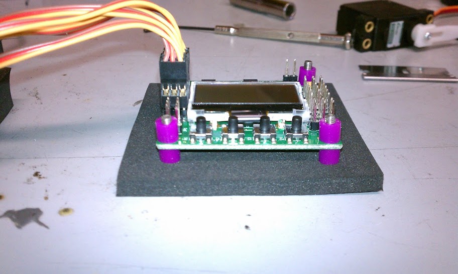 Here is the board mounted, with additional protection:  And here is my make-shift KK2 protection plate. I drilled it out of some spare Lexan, but this stuff scratches easily and im sure soon I wont be able to see through it any longer: 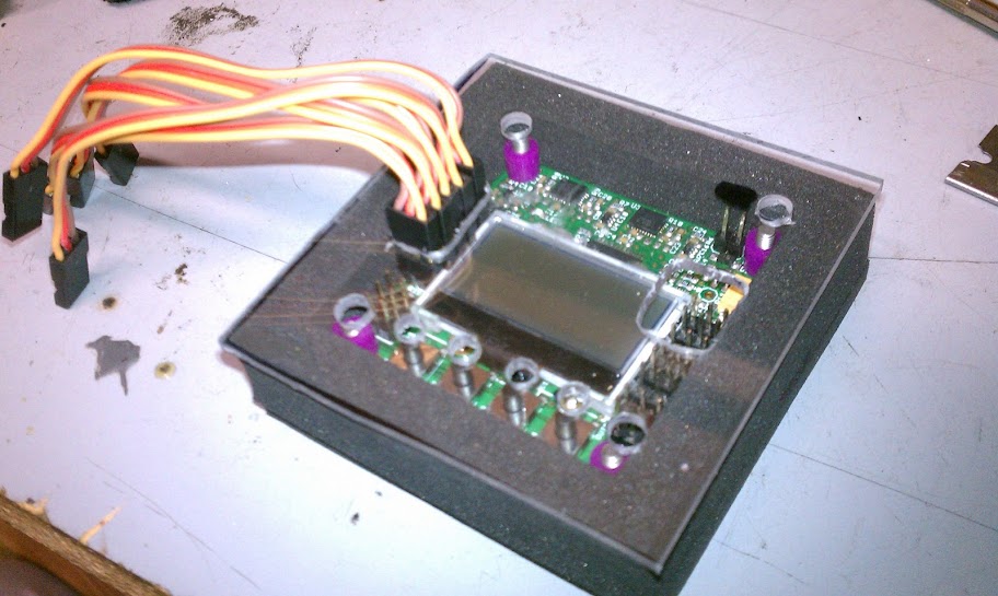 Here's a simple pic of my Arm with the ESC mounted and prepared for flight: 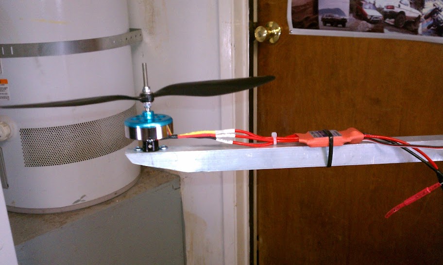 Yes I know... i plan on cutting down the prop shaft before everything is said and done. But the props are mounted using 4mm nylocks, two on each shaft and washers on each side of the prop. It seems to do the trick. Here I have some video of me bench testing Motor 1 & 2. I lucked out and mounted the right motors to the right arms, and they spin towards eachother as planned
And here we have some video of me using my cellphone and a vibration meter to test for balance:
I also realized I am getting Yaw Servo Jitter  But only at higher RPM's... which im hoping will be fixed when I flash the latest KK firmware to my board. But only at higher RPM's... which im hoping will be fixed when I flash the latest KK firmware to my board.
|
||||
|
|
Last edited by AcroFPV; Aug 23, 2012 at 05:58 PM.
|
||||
«
Previous Thread
|
Next Thread
»
| Thread Tools | |


| Similar Threads | |||||
| Category | Thread | Thread Starter | Forum | Replies | Last Post |
| Build Log | First Tricopter build | smoking91awd | Multirotor Drone Talk | 4 | May 03, 2013 07:01 PM |
| Discussion | Tricopter first flight | Theladon | Scratchbuilt Multirotor Drones | 9 | Aug 07, 2012 04:03 AM |
| Build Log | My first adventure in flight... a Tricopter Build | AcroFPV | Multirotor Drone Talk | 6 | Aug 02, 2012 11:08 PM |
| Help! | I need tips for my first fpv on a tricopter | jordanmeir | FPV Talk | 10 | Jun 24, 2012 09:46 PM |
| Discussion | Building my first tricopter! Questions | faheja | Multirotor Drone Talk | 1 | Feb 23, 2012 10:51 PM |