|
|
|||||
|
Thread OP
|
Build Log
DIY Headtracker (Easy build, No drift, OpenSource)
Time for a new DIY and OpenSource-project
 A couple of fellow FPV-friends complained about their headtrackers - mainly drift problems and bad resolution. One showed a video with the problem, and my comment "that looks really bad, even I can make that a lot better", ended up costing me a bit of time. I have choosen to use 3 axis- accelerometer, gyro and magnetometer, as that's the only way to account for drift in all directions. Flight video from Gabek
Quick video from absolute-zero:
The hardware used is pretty simple, you just need an Arduino and a sensorboard. Arduino Nano: 11.99$ shipped: http://www.dealextreme.com/p/nano-v3...-118037?item=8 or: 12.28$ shipped: https://www.hobbyking.com/hobbyking/s...ler_Board.html or: 16.90$ shipped: http://www.dealextreme.com/p/arduino...0-81877?item=2 Sensor board (9-axis IMU): 18.30$ shipped: http://www.dealextreme.com/p/gy-85-6...arduino-148436 33.49$ shipped: http://www.ebay.com/itm/ws/eBayISAPI...E:L:OC:US:3160 or: 29.51$ shipped: http://www.goodluckbuy.com/gy-85-sen...u-sensor-.html Perhaps this one is the same? 19.67$ shipped: http://www.goodluckbuy.com/nine-axis...3l-module.html That's about 30$ total Code and GUI can be found at google code http://code.google.com/p/open-headtracker/ And that's it. The project is made as user-friendly as possible, and only little technical knowledge should be necessary. All necessary settings can be changed from a graphical user interface - making it easy for everyone to use. All good ideas for improvement is more than welcome Connection diagram/pinout: Connection diagram for Pro mini (made by typicalaimster) 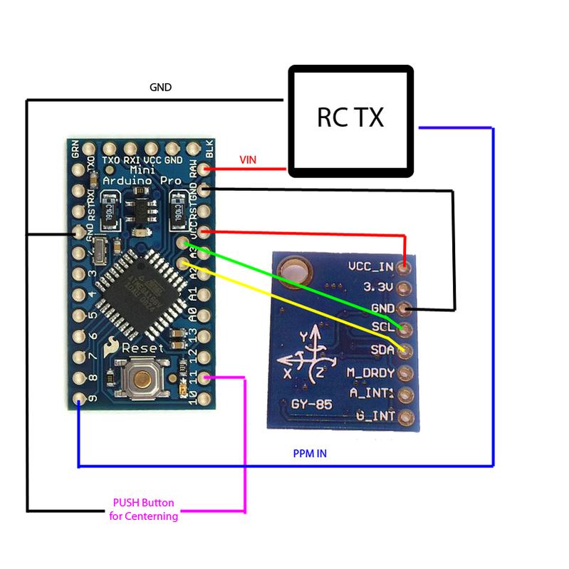 The hardware used: Assembled hardware - just missing connections to RC-transmitter Early test-version. Plug-n-play in FF9 transmitter. Graphical user interface - GUI showing advanced settings too: GUI for magnetometer calibration: Tests with PPM expansion (this part is not done): PPM in from FF9 (red), PPM out from tracker (blue): 8 channel PPM in, 12 channel PPM out (this part is only : Constant frame-rate (red: FF9 PPM in, blue headtracker PPM out) Headtracker sensor plots, raw, filtered etc: A quick test-video can be found here. It's hard to show if a headtracker works well or not, so it's just a quick test-video. https://dl.dropbox.com/u/3947315/Videogdp.3gp Short description of the more technical stuff ---------------------------------------------------------- Headtracker: The sensors are sampled with 128 samples/sec. As we have 9 sensors, we get 128 * 9 = 1152 measurements/samples every second (more than plenty for a headtracker). The sampling-rate is controlled by timer0, that will set a flag high - indicating that the sensors should be read and new angles etc. calculated (timer0 running in CTC-mode, using compare-register A). While it should be possible to make all the calculations etc. within the interrupt, it's not recommended. A lot of heavy/slow calculations are done, and in case of timing-problems, we just want it to skip a sample and continue (should never happen, but just in case). If you turn on DEBUG you will get a lot of extra information, be able to see timing-problems etc. (please note, using serial.print is time comsuming and will in mast cases give timing-problems. Rarely a real problem when debugging, but be aware that it will change the samplerate a bit.) Accelerometer: The accelerometer data is converted to G-force. Not really necessary, but more convenient to work with. The total G-vector is calculated, and the angle calculated by using the total vector-length and the G-force in each direction. Gyro: The gyro indicates the angular change in degrees/sec. All axes accounts for tilt etc and data is continously integrated, to give an estimation of the angle. Magnetometer: The magnetometer is compensated for tilt (x- y-direction), and the final x and y values used to calculate the magnetic heading. Filter: The filter is a basic complementary filter, and an optional lowpass filter. The weight for gyro/accelerometer/magnetometer can be sat in the GUI, and lowpass filter changed. PPM Please note that only PPM-out is activated as default. PPM-mixing etc. need some work. The PPM in/out is a bit tricky, as we can only do one thing at a time. Oh - and we only have one 16 bit timer available. Timer1 (16 bit timer) is used to generate the PPM output. It's set to change pin at interrupt to get an accurate hardware-timed pin-change. The compare-interrupt will set the next compare-match. PPM-in is detected by pin-change interrupt (higher priority than timer1 compare interrupt). It will use the time from timer1, and detect if the timer have been reset. ---------------------------------------- A few notes: Use of Serial output The headtracker uses a lot of slow calculations with floating points, cos, sin atan etc. Furthermore the sampling frequency is pretty high. Using Serial.print is great for getting info, data etc. - but it requires time. As it's running "on the edge", you can only print a few characters without loosing a sample. It's programmed to just skip a sample in case of timing problems, but just be sure to note this when testing. Updating variables All variables stored in EEPROM have to be changed in the GUI or by changing this: // If the device have just been programmed, write initial config/values to EEPROM: if (EEPROM.read(0) != 42) { But as all settings saved in EEPROM can be changed from GUI I'll suggest that, as it's a lot easier. ---------------------------------------- Using the GUI: The GUI have been changed quite a bit since first versions, and is hopefully pretty intuitive. PPM channels Used to set the PPM-channel pan/tilt and roll is assigned t0 Center The center position of the servo End Servo travel end. Gain The gain determines how much the servo should move for a given head-movement. Default is 170 which pretty much gives 1:1 (90 degrees head-movement = 90 degrees servo movement). All the "advanced settings" - - - - LP filter at tilt/roll [%] Lowpass-filter of the final tilt/roll output. 1 = max lowpass/time constant. Will give very smooth, but also very slow change. 100 = lowpass off. LP filter at pan [%] Lowpass-filter of the final pan output. 1 = max lowpass/time constant. Will give very smooth, but also very slow change. 100 = lowpass off. Gyro weight on tilt/roll [%] How much do we thrust the gyro compared to the accelerometer on the tilt/roll axis? Accelerometer is noisy and should only be used to slowly compensate for drift. 100 = only use gyro. 0 = only use accelerometer Gyro weight on pan [%] How much do we thrust the gyro compared to the magnetometer on the pan-axis? The gyro is a lot more accurate, so magnetometer should only be used to slowly compensate drift. 100 = only use gyro 0 = only use magnetometer Servo pulse variation In short: Servo travel adjustment. Used to set the max variation of the pulse-width in the PPM signal. The unit is microseconds*2 - matching the Atmega timer Servo center In short: Servo neutral position Used to set the center/default length of the pulse-width in the PPM signal. The unit is microseconds*2 - matching the Atmega timer Tilt and roll gain Gain of the servo. You decide if you want to turn the head 10 degrees or 360 degrees to get full travel. Pan gain Gain of the servo. You decide if you want to turn the head 10 degrees or 360 degrees to get full travel. Reverse (Tilt, roll and Pan) used to inverse the servo direction. ---------------------------------------- General questions: Can I use other Arduino versions? Sure, all Arduino boards should have the necessary pins available (as far as I know). I have choosen Arduino Nano as it's cheap, small, have FTDI onboard and the regulator can handle a bit higher current, compared to Arduino Pro etc. But pick whatever you prefer/have available. Can I use other sensors? It should be pretty easy to use other sensors, as long as it's I2C. Update the sensor-init, sensor-reading and the sensor-configuration and you should more or less be good to go. I'll maybe add support for another IMU later. Can I buy a headtracker from you? No, it's meant as a DIY project. It's easy to make, and it should be pretty straight forward. I like to develope, but care little about sale etc.  Can I sell this? Feel free. I can imagine a few people would like to buy a nice ready-made unit, but it would be great to know if you use my software/work. But in general it's uploaded with no strings attached. What about copyright/license etc? It's uploaded as OpenSource, and I expect it to be used and abused - don't really see much sense in "protecting" my work. So feel free to use it for whatever purpose. Quick guide Okay, quick little "start guide" for those not familiar with Arduino You should have: 1 x Arduino Nano or similar 1 x IMU/sensor board
Hopefully that's it, and you are ready to go. Some known limitations:
Few pictures from other peoples build: SpookiePower   SubSonic:   Jalves: BlueAngel Absolute-Zero Donations kindly received from: - Guy1a - Gabek - typicalaimster - ChilternFlyer - Quadzimodo |
||||
|
|
Last edited by Dennis Frie; Oct 21, 2013 at 01:41 PM.
|
||||


|
|
 i am on my way to heaven.
 |
|
||
|
Thread OP
|
Quote:
I'm pretty confident that you are not gonna hit the reset button even once on this tracker - but that's probably due to the fact, that it doesn't have one yet.  On a more serious note. When the center-position have been set, you shouldn't notice any drift at all. It will continuously account for drift using accelerometer and magnetometer. You can try to provoke drift all you want, but with normal head-movements I doubt you will notice anything. If you want to test how it works, grab the tracker in the wires and give it a good "swing". You should be able to get it off course. Then center the headtracker again, and see how fast it centers
|
|
|
|
Last edited by Dennis Frie; Jun 25, 2012 at 11:12 AM.
|
|
|
|
|
|
|
Woot! Nice, and subscribed.
|
|
|
|
|
|
||
|
Thread OP
|
Quote:
It would be great with a few to test it. Im open for ideas, improvements etc. http://code.google.com/p/open-headtracker/ Thanks |
|
|
|
||
|
|
|
|
Thread OP
|
And yes, I know schematic etc. is still missing, but its more or less all software this time. This is all the connections necessary
*Green wire to RC transmitter is only for later headtracker PPM in. |
|
|
|
|
|
|
|
|
wow, thats really great Dennis.
thank you very much. I am using the Flytron magnetic headtracker, works good with no drift. BUT, i have to always look to south or north, which is sometimes annoying. This one will solve all this problems. 
|
|
|
|
|
|
||
|
Thread OP
|
Quote:
Year I've heart the headtracker from Flytron should work great - but the north/south is annoying. Hopefully this project will solve at least some of the problems. The first test-version is released, so time to get some feedback and fine-tune the tracker. I'll add another option in the GUI soon so you guys can test more or less all parameters if you want. |
|
|
|
||
|
|
|
|
|
Yes, the Flytron was the only headtracker, which works really good.
(tested already track-R2 and XGY1000) I have already ordered the sensor board. For the Arduino, i will use a Pro Mini board. Are there no Pull-Ups needed for the SDA and SCK signal lines? The Wii project uses now 2,2k to 5V to have an stable I2C bus. |
|
|
|
|
|
||
|
Thread OP
|
Quote:
I'll try to have a better schematic etc. ready before you receive the hardware, but it's pretty straight forward to connect.4 wires/connections to sensorboard and 3-4 wires to RC-transmitter. So far it have worked flawless without any extra pull-ups at the I2C bus. As the voltage is pretty clean from the RC transmitter, regulated by a 5-volt regulator on Arduino and afterwards a 3.3 volt regulator on the sensorboard, I doubt it will be necessary. |
|
|
|
Last edited by Dennis Frie; Jun 26, 2012 at 05:35 AM.
|
|
|
|
|
|
|
Okay, good to now.
Makes it just simpler to connect. I will use this headtracker again with the 433MHz PPM expander from this thread here: https://www.rcgroups.com/forums/show....php?t=1227871 currently mine looks like this: https://www.rcgroups.com/forums/show...6&postcount=65 Will build everything on the top of my Cinemizer Plus goggles + a small receiver for video and audio, to have absolutely no cables between ground station and goggles and headtracker and radio transmitter. |
|
|
|
«
Previous Thread
|
Next Thread
»
| Thread Tools | |


| Similar Threads | |||||
| Category | Thread | Thread Starter | Forum | Replies | Last Post |
| Build Log | Diy osd (Arduino and opensource) | Dennis Frie | FPV Equipment | 2526 | Sep 04, 2022 06:55 AM |
| Discussion | PPM to PWM circuit for headtracker | 38cjc38 | DIY Electronics | 20 | Jun 07, 2020 03:08 AM |
| Question | Adding additional PPM inputs to a headtracker/module setup. | SebastianJ | FPV Talk | 0 | Aug 19, 2009 07:38 AM |
| Question | Adding additional PPM inputs to a headtracker. | SebastianJ | DIY Electronics | 0 | Aug 18, 2009 03:37 PM |