Thread Tools
Oct 27, 2011, 08:14 PM
Registered User
Quote:
Originally Posted by Dennis Frie
That's great
You might want to add the dimming-resistor as well. The dimming makes it a lot easier to read the text on a bright sky etc. You can always turn it off in the software if you don't like it.
Where do i add that?
Sign up now
to remove ads between posts
Oct 27, 2011, 08:21 PM
Just another user
Dennis Frie's Avatar
Thread OP
Just went quickly through the thread, I figured it would be fun to collect a few images from peoples build


Oct 27, 2011, 08:25 PM
Just another user
Dennis Frie's Avatar
Thread OP
Quote:
Originally Posted by p3jpaavi
Where do i add that?


In this schematic it's the resistor called R2. You just connect the video to pin 8 through a resistor. The resistor value can be changed to adjust how dark a background you want.
Oct 27, 2011, 10:49 PM
Registered User
Just got mine up and running on a bread board last night! Just need to etch a PCB and I'll be good to go for testing it out in flight this weekend! Here's a pic of what I have so far. My GPS runs off of 3.3v so I threw in a voltage regulator and a logic level converter from Sparkfun.

Thanks for the great project Dennis! You're awesome!
Oct 28, 2011, 02:37 AM
Registered User
hi,

anybody an idea what is going wrong here? i built the osd on a breadboard and on a circuit board but the output is exactly the same. i took the same values for the parts as in post #1.

Oct 28, 2011, 02:53 AM
Electronics slayer
SouthPawPaul's Avatar
Looks like you need to give the variable resistor a twiddle
Oct 28, 2011, 05:30 AM
Just another user
Dennis Frie's Avatar
Thread OP
Great to see guys

Quote:
Originally Posted by JayPi
hi,

anybody an idea what is going wrong here? i built the osd on a breadboard and on a circuit board but the output is exactly the same. i took the same values for the parts as in post #1.

Jaypi, as SouthPawPaul said try to give the variable resistor a twist. But it looks like your text is pretty close to the right edge, that will give exactly the effect you see (you can see the same effect on the menu-test video when text-align is "pushed over the edge").

Try to change this (line numbers from version 16):
Line 73: #define align_text_ 22
Change to: #define align_text_ 14 (14 is probably too low, but just to check if it helps to move the text to the left).

Line 130: #define reset_values 0
Change to: #define reset_values 1

Please let me know if that fixed the problem
Oct 28, 2011, 06:29 AM
Registered User

newbie questions


As it is said in the title i'm a newbie here, so don't be angry if my questions are silly

1) I have found 2 different schematics for this osd, which one is the right one?
a)

b) here is the difference in how potentiometer is connected or it makes no difference?


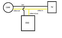
2) there is only one pin for video and it is marked as video in/out on b). And no video pin on a). So how do i connect the OSD. I thought that osd must stand between the cam and video tx/tv

3) is there a schematics on how to connect the current sensor

Thanks
Oct 28, 2011, 06:34 AM
Registered User
Quote:
Originally Posted by Dennis Frie
Great to see guys


Jaypi, as SouthPawPaul said try to give the variable resistor a twist. But it looks like your text is pretty close to the right edge, that will give exactly the effect you see (you can see the same effect on the menu-test video when text-align is "pushed over the edge").

Try to change this (line numbers from version 16):
Line 73: #define align_text_ 22
Change to: #define align_text_ 14 (14 is probably too low, but just to check if it helps to move the text to the left).

Line 130: #define reset_values 0
Change to: #define reset_values 1

Please let me know if that fixed the problem
Hi,

I had pretty much exactly the same distortion from memory.
Moving the text left as suggested above did help, but I still had some wierdness (e.g. notice that the first '0' on the timer is fatter than the others?)

I eventually discovered by accident that switching compiler versions made it work perfectly! avr-gcc (as used by arduino ide) on Ubuntu 11.10 had the distortion as above, but avr-gcc in Ubuntu 11.04 did not!

Dennis, can you tell us which gcc you develop with? (gcc --version) is it the one shipped with arduino-022 for windows?

Dave
Oct 28, 2011, 06:52 AM
Registered User
hi,

i will eat my hat!!! it was the compiler. tried it now with ubuntu 11.04 and the osd output is brilliant! compiler version is now 4.3.4.
thank to all for your help.

joerg
Oct 28, 2011, 10:05 AM
Just another user
Dennis Frie's Avatar
Thread OP
Quote:
Originally Posted by aSa2
As it is said in the title i'm a newbie here, so don't be angry if my questions are silly

1) I have found 2 different schematics for this osd, which one is the right one?
a)

b) here is the difference in how potentiometer is connected or it makes no difference?


2) there is only one pin for video and it is marked as video in/out on b). And no video pin on a). So how do i connect the OSD. I thought that osd must stand between the cam and video tx/tv

3) is there a schematics on how to connect the current sensor

Thanks
The schematics are exactly the same, only difference is the dimming/pixel resistor values R1 and R2. The video in/out is not shown in first schematic, but it should be placed as shown in the other schematic.
First schematic is "classic style" with ground in bottom etc. The second one is made for Arduino Pro to match the pinout etc.
The potentiometer is connected the same way on both schematics? It doesn't matter if you turn it around 180 degrees, it's just a resistor.

You can connect the OSD as you like, it doesn't have to be "between" camera and video-tx. You can just split the video-output (from the camera) and connect the OSD to one wire and the video-tx to another wire.

Regarding current-sensor, the schematic is shown in the datasheet (carefull, the first "drawing" in the datasheet has wrong pinout).

If I get time I will update the schematic this weekend to include GPS, voltage and current sensor.
Oct 28, 2011, 11:20 AM
Registered User
Quote:
Originally Posted by Dennis Frie
The schematics are exactly the same, only difference is the dimming/pixel resistor values R1 and R2. The video in/out is not shown in first schematic, but it should be placed as shown in the other schematic.
First schematic is "classic style" with ground in bottom etc. The second one is made for Arduino Pro to match the pinout etc.
The potentiometer is connected the same way on both schematics? It doesn't matter if you turn it around 180 degrees, it's just a resistor.

You can connect the OSD as you like, it doesn't have to be "between" camera and video-tx. You can just split the video-output (from the camera) and connect the OSD to one wire and the video-tx to another wire.

Regarding current-sensor, the schematic is shown in the datasheet (carefull, the first "drawing" in the datasheet has wrong pinout).

If I get time I will update the schematic this weekend to include GPS, voltage and current sensor.
Thanks for your answer and just to be sure, is that correct?
Last edited by aSa2; Oct 28, 2011 at 01:03 PM.
Oct 28, 2011, 11:29 AM
Just another user
Dennis Frie's Avatar
Thread OP
Quote:
Originally Posted by aSa2
Thanks for your answer and just to be sure, is that correct?
Jep, that's perfect.
(You have written V-out and V-in, I suppose that's Video-out/in and not voltage-out and voltage-in )
Oct 28, 2011, 12:05 PM
Registered User
rimshotcopter's Avatar
Thank you Dennis for this great project. I now have the LM1881 working with your code and the video quality is OUTSTANDING! I now need to wire in the GPS and give this puppy an air time. I have the transmitter/receiver order.


DYI-OSD with LM1881 (0 min 10 sec)


I will attempt to make a simplified draws.
Oct 28, 2011, 12:32 PM
SX_
SX_
.........lost..........
Quote:
Originally Posted by rimshotcopter
Thank you Dennis for this great project. I now have the LM1881 working with your code and the video quality is OUTSTANDING! I now need to wire in the GPS and give this puppy an air time. I have the transmitter/receiver order.


http://www.youtube.com/watch?v=xhPrn2DnS2M

I will attempt to make a simplified draws.
THAT IS COOOOL


Quick Reply
Message:

Thread Tools

Similar Threads
Category Thread Thread Starter Forum Replies Last Post
Discussion Diy osd karl k FPV Talk 2 May 03, 2011 12:31 AM
Idea New DIY OSD? atari7202 FPV Talk 1 Mar 25, 2011 12:08 AM
Discussion see my own diy OSD video Passion Aerial Photography 7 May 27, 2010 01:28 AM
Discussion REAL homebrew DIY OSD - Check it out! jafoca FPV Talk 8 Jun 29, 2009 06:52 PM
Discussion picoOSD DIY PIC12F683 based OSD in C kbosak FPV Talk 6 Jan 31, 2008 08:47 AM