Probedude's blog View Details
Posted by Probedude | Oct 28, 2007 @ 05:34 PM | 14,316 Views
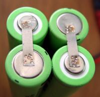
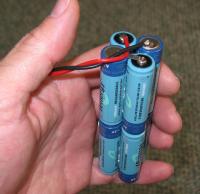
Here's a receiver pack made up from button top NiMH cells. My Hitec Flash5x and DX6 transmitter will both hold this size pack though it was made from button top cells.
Posted by Probedude | Oct 27, 2007 @ 01:32 PM | 93,522 Views
I've been needing one of these for a long time and finally put one together.

The design came from this website http://www.philpem.me.uk/elec/welder/

The author there used 5 qty 120,000uF 25VDC caps for his capacitor bank. I scoured Ebay and missed out on a few auctions for similarly rated caps but then saw a good deal on 100,000uF 15VDC caps. Thinking that 15VDC max would do it, I bought 8 qty off Ebay for ~$40 delivered. Hopefully by minimizing the resistance of all the conductors, 15VDC will work.

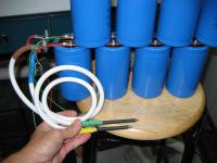
Caps came and the were BIG and HEAVY! Pretty impressive.

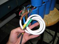
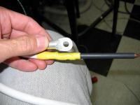
I decided to mount them as you can see in the pictures below. With 8 capacitors, if they were all linearly arranged in a single level, the pack and the bus bars would need to be pretty long. Stacking them shortened the length of the pack and the bus bars and also minimized the electrical losses. I extended the bus bars 1" past the last capacitor so I could bolt on my cable. Bus bars were bought through McMasterCarr and are 1/16" thick, 1/2" wide copper. A Whitney punch was used to punch clean, perfect holes into the bar for mounting the caps.

The SCR purchased (IR 50RIA20) is the same as used by the author and was bought from Newark for ~$18. I originally wanted to get an SCR with a heavy flexible cathode cable but those were nearly 3X the price. The 50RIA20 has a continuous amperage rating of 50A, but a surge peak of 1480amps.
Here's the datasheet
http://www.irf.com/product-...Continue Reading
Posted by Probedude | May 25, 2007 @ 11:13 PM | 15,705 Views
Cellpro 4A version - differences and similarities to the 3A version
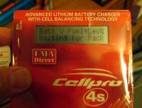
I received a Cellpro4s, 4A version with the new display today. I purchased it to send to a fellow RCGroups member in another country.

Looking it over carefully and only through the heatshrink outer covering, the 4A version of the Cellpro is pretty much identical to the 3A version - differences noted below.

- different inductor - or at least this time it has heat shrink around it. I wonder if some units rubbed the enamel off the inductor and the soldermask off the PCB and they shorted so this is the fix.
- step up mosfet is now the same as the input polarity mosfet (FDS6690a)
- step down mosfet is now an FDS4435 - this is a 9A (or 8.8A) P-channel mosfet. This replaces the 5A version in the previous Cellpro model. I've repaired 3 Cellpros and this mosfet was shorted in 2 of them.

All the rest of the significant components that I can see and read are the same:
- mosfet driver
- forward biased schottky
- flyback shottky
- input and output polarity protection/current sense mosfets, etc.

Other than programming, the step up and step down mosfet change and maybe a new inductor, I can't see anything else new. I'm guessing the main reason for not offering upgrade service for the 3A to the 4A version is it would be too expensive to swap out those 3 components, update the firmware and recalibrate the unit.

Cellpro - the 50W charger
The new 4A version cellpro is quite similar to the 3A version....Continue Reading
Posted by Probedude | Apr 29, 2007 @ 12:59 AM | 15,064 Views
Cellpro Repairs
I recently repaired another user's Cellpro that was overvoltaged. In his case the step down and step up mosfets and their mosfet driver IC was blown. Replacing these components fixed his Cellpro. Parts cost was ~$4.00

Another user accidentally blew out his input polarity mosfet when their cellpro touched the + terminal of their car's battery. I haven't yet received it to see if anything else blew, but I doubt it. The Cellpro's input polarity protection is a N-ch Mosfet on the negative input lead. When the lid touched the car battery's + terminal, this shorted the input polarity mosfet directly across the battery.

Update:Received his Cellpro and indeed only the input polarity protection mosfet was blown. Replacing it, his cellpro is again functioning.

Cellpro's Polarity Protection and DC-DC Converter Circuit
The Cellpro's DC-DC converter is setup as a Buck-Boost switching regulator that is controlled by the TI Microcontroller through a mosfet driver IC. The active components and inductor are as follows (pricing as of 4/28/07)

- input and output polarity mosfets, mfgr = Fairchild, pn FDS6690a 11A 30V N-ch soic8 pkg
Digikey pn FDS6690ACT, $0.80 each

- step down mosfet, mfg = Rohm, pn RSS050P03TB 5A 30V P-ch soic8 pkg
Digikey pn RSS050P03TBCT, $1.01 each

- step up mosfet, mfg = Rohm, pn RSS090N03TB 9A 30V soic8 pkg
Digikey pn RSS090N03TBCT, $0.75 each

- mosfet driver TC1427COA, mfgr = MicroChip, non-inverting 1.2A soic8 pkg
...Continue Reading
Posted by Probedude | Mar 28, 2007 @ 08:52 PM | 15,370 Views
Figured out the display issue with some Cellpro chargers.
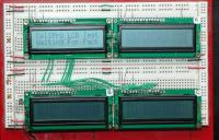
The are 2 different revision levels of the LCD display being used, but both revision have the same part number.

Version 1 displays look fine head on.
Version 1.2 displays are faint head on.

The same value contrast setting resistors are used regardless of the version LCD installed. To fix the problem, Cellpros with version 1.2 displays need their contrast resistor divider values changed.

The end user can perform this 'adjustment' by tacking a 470 ohm resistor on pins 1 and 3 of the LCD pads on the main Cellpro PCB. I've been told this voids the warranty, but the modification is very simple and I feel safe. FMA does not offer this service.

See here for more information.
https://www.rcgroups.com/forums/show...87#post7171087

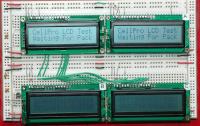
Here's 2 pictures showing the version 1.2 display before and after the contrast resistor adjustment is made.
(Upper left display is version 1, all other displays are version 1.2).
Posted by Probedude | Nov 09, 2006 @ 01:42 AM | 17,621 Views
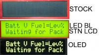
BACKLIT SUPERTWIST LCD DISPLAY UPGRADE
Finally decided to upgrade the display on my Cellpro4S charger. Relatively painless and a HUGE jump in readability, even in daylight (I was 'lucky' enough to get a bad unit to begin with).
Details here:
https://www.rcgroups.com/forums/show...63#post6340763


CELLPRO CONSTRUCTION
Also spent some time looking over the construction of the Cellpro4S. Quite simple in layout, total BOM. Very clean. I'll scope out some of the signals lines later whenever I get any free time, especially interested in looking at the FET drive signals with various input voltages and pack voltages.

https://www.rcgroups.com/forums/atta...mentid=1284494


OLED DISPLAY UPGRADE OF THE CELLPRO4S
https://www.rcgroups.com/forums/showthread.php?t=654183

Here's where I retrofitted my brother's Cellpro4s with an OLED display. Still looked good in the sunlight yesterday.