Archive for August, 2013
Posted by Jack Crossfire |
Aug 31, 2013 @ 12:16 AM | 8,546 Views
Owner knows why drone crashed into stands at bull run
Found the story intriguing. Batteries remane fickle things. Their total charge is still only estimated by stopwatches & coulomb counters, but there is no dip stick for a battery. Even a pilot experienced enough to keep 1 eye on the flight time while the other eye is on the 5000 other details still is often surprised when a battery comes up empty ahead of schedule.
Sometimes you forget to charge batteries. Battery chargers sometimes don't finish charging because they overheat or their own supply sags. Sometimes they don't start charging because of a balky button or a poorly designed user interface. Sometimes they report maximum voltage despite no longer holding a full charge.
A return to launch feature when the battery is low also remanes fickle. GPS comes & goes anywhere besides a wide open field. Is the return to launch feature supposed to count coulombs & maintain a database of every battery's capacity in order to determine when to end the flight? Should the pilot enter in the current battery ID or should the batteries have ID chips, raising the cost & complexity?
It's yet another one of the variables & details that keeping something in the air still involves keeping your mind on. There is still a lot of room in the current state of reliability to keep the price, complexity & training beyond the reach of hobbyists before the personal drone becomes as ubiquitious & hand off as the marketing campaigns depict.
Comments (0)
Add Comment
Posted by Jack Crossfire |
Aug 29, 2013 @ 07:38 PM | 8,703 Views

So a phone still can't outdo a dedicated mp3 player for a car. After the Sansa broke again, it was a rough 10 hours of driving, fighting the Android music app & getting mono audio out of its 4 conductor headphone jack.

...Continue Reading
Posted by Jack Crossfire |
Aug 29, 2013 @ 07:09 AM | 9,012 Views
The final Delta IV heavy ever to be launched from Vandenberg lifted off on time, again. Had a much better camera than 2011. After much fog & drizzle, the fog cleared 1 hour before launch.

Floradale Ave had a better view of all 3 boosters than Surf beach & the weather was also better than 2011.

But Surf beach had better sound. Tried recording the sound, but had the gain too low. It was hardly louder than a passenger plane. There's no automatic gain.
...Continue Reading

Floradale Ave had a better view of all 3 boosters than Surf beach & the weather was also better than 2011.

But Surf beach had better sound. Tried recording the sound, but had the gain too low. It was hardly louder than a passenger plane. There's no automatic gain.
...Continue Reading
Posted by Jack Crossfire |
Aug 23, 2013 @ 09:12 PM | 8,585 Views
Launch preparations continue
The problem with lens test patterns is they're all photographs through other lenses & they're all greyscale. A printer can't print greyscale. It can only print halftones which convert your test pattern to dots. So you convert the test pattern to 1 bit & get aliasing artifacts.
The camera used on the 1st Delta IV launch was an el cheapo Sanyo, which could only achieve this quality from the test pattern:

Its best view of the rocket was:

The 2nd & final launch is going to be captured by a DSLR which achieves this quality:
...Continue Reading
The problem with lens test patterns is they're all photographs through other lenses & they're all greyscale. A printer can't print greyscale. It can only print halftones which convert your test pattern to dots. So you convert the test pattern to 1 bit & get aliasing artifacts.
The camera used on the 1st Delta IV launch was an el cheapo Sanyo, which could only achieve this quality from the test pattern:

Its best view of the rocket was:

| Delta 4 heavy launch (2 min 57 sec) |
The 2nd & final launch is going to be captured by a DSLR which achieves this quality:
...Continue Reading
Posted by Jack Crossfire |
Aug 23, 2013 @ 06:00 AM | 7,659 Views
So for the VCO driving voltage, the manufacturer has a data table which can be interpolated & compared to the mathematically derived curve.


...Continue Reading


...Continue Reading
Posted by Jack Crossfire |
Aug 22, 2013 @ 06:01 AM | 7,829 Views
Goog searches for radar are about as useful as goog searches for IMU's were, 7 years ago. They haven't reached the mass consumer usage that it takes for something to yield useful results, but you know radar is going to be the next IMU in every phone.
There is a guy who plays with radar.
http://mrvacuumtube.blogspot.com/
Notably, he used a bandpass filter as a range gate. Perhaps a range gate filter could knock out reflections in the module itself that saturate the amplifier. He also has example videos of radar images, which are few & far between.

B-52 scale model.

F-14 scale model
...Continue Reading
Posted by Jack Crossfire |
Aug 21, 2013 @ 02:54 AM | 8,051 Views
Finally hit the Zoom H2 with the radar output. The Zoom H2 uses the TLV320AIC32, the highest quality ADC in the apartment.

A quick comparison revealed no significant difference in the range of interest.
It turns out while the Zoom H2 records 24 bit files, its ADC documentation never specifies how many bits it records. It oversamples at 128x to fill in extra bits. It seems to convert 19 unique bits. There's a 528 sample section at the beginning of every file where only 19 bits are written.
It definitely can receive reflections from materials other than metal, but not in FMCW mode. In doppler mode, the gain can be increased to 1000x, where it detects wood & body parts. The problem with doppler is it can't detect slow movement.
So the problem with detecting non metallic materials is the gain, which is limited by very a large low frequency component in the signal. It would take an unreasonably sharp filter to cut it off.

Also tried sinusoidal frequency modulation, which made even more low frequency offset.
Finally, a video showing how well the radar works, including its inconsistencies.
That was using single pass 256 ksamples/sec 1024 sample windows.

A quick comparison revealed no significant difference in the range of interest.
It turns out while the Zoom H2 records 24 bit files, its ADC documentation never specifies how many bits it records. It oversamples at 128x to fill in extra bits. It seems to convert 19 unique bits. There's a 528 sample section at the beginning of every file where only 19 bits are written.
It definitely can receive reflections from materials other than metal, but not in FMCW mode. In doppler mode, the gain can be increased to 1000x, where it detects wood & body parts. The problem with doppler is it can't detect slow movement.
So the problem with detecting non metallic materials is the gain, which is limited by very a large low frequency component in the signal. It would take an unreasonably sharp filter to cut it off.

Also tried sinusoidal frequency modulation, which made even more low frequency offset.
Finally, a video showing how well the radar works, including its inconsistencies.
| Radar test 2 (3 min 5 sec) |
That was using single pass 256 ksamples/sec 1024 sample windows.
Posted by Jack Crossfire |
Aug 20, 2013 @ 01:51 AM | 8,396 Views
The shape of the frequency ramp is the biggest factor in your radar range. Ideally, the VCO would generate a linear frequency ramp from a linear voltage ramp, but this probably never happens. The VCO is an open loop controller, since it has to make thousands of ramps each second.
The following is the most optimum ramp, so far:

Unfortunately, it doesn't agree with the datasheet's voltage ramp. Without a spectrum analyzer, there's no way to get a perfectly linear frequency ramp. There may be a feedback loop in practical systems which adjusts the voltage ramp based on ghosting in the image.
After much kiwipedia graph searching, the nearest function to the nonlinear VCO ramp was:
STEPS=1024
MAX=4096
EXPONENT=0.5
x range = 0 ... STEPS
y range = 0 ... MAX
y = pow(x * 2 / STEPS, EXPONENT) * MAX / 2;
y = y * curve_weight + x * MAX / STEPS * line_weight;
The magnitude & eccentricity of the curve can be changed by changing the exponent & blending it with a straight line.
Then came some experiments to minimize the blurring on the spectrogram with various curve weights at exponent 0.333.

There was a tradeoff between intensity of the target & ghosting. The datasheet ramp produced a very intense target with lots of ghosts.
...Continue Reading
Posted by Jack Crossfire |
Aug 19, 2013 @ 12:55 AM | 8,126 Views

So after stacking 16 waveforms, still using the nonlinear frequency sweep, a metal reflector finally started to appear in the image. It was the 1st time any radar modulation showed anything. Also, when the metal reflector was moving, it disappeared. It only had 1 foot range & couldn't sense anything besides the reflector. Things would be better with a linear frequency sweep.
There is a point in averaging waveforms where increasing the number of averaged waveforms reduces the detected signal. There is a ripple in the frequency modulating which makes later waveforms cancel out earlier waveforms. More stacking also requires running the ADC faster.
It's not bad for a single chip radar, but reveals why radar guidance on this scale probably still isn't workable. After reviewing sample waveforms & experiencing what the imaging entails, the mane problem is power. The single chip solution doesn't put out enough power to do the 20 scans per second to construct a 1D image or the 400 scans per second for a 2D image.
Even weather & air traffic radar is limited to very slow scan rates by power.
Posted by Jack Crossfire |
Aug 18, 2013 @ 03:11 AM | 7,804 Views


Posted by Jack Crossfire |
Aug 17, 2013 @ 04:04 AM | 8,341 Views
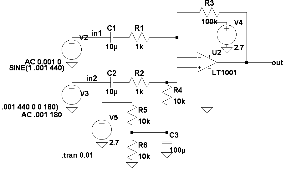
LTSpice is a heap of crap free program intended to sell LT parts, but it's the 1st time a practical circuit simulated in a spice program actually worked in real life.

The challenge was to amplify a differential signal in the microvolt range to an offset signal a microcontroller could capture.

It did indeed work in simulation & real life. The real op-amp ended up a prime spec MAX412.
...Continue Reading
The challenge was to amplify a differential signal in the microvolt range to an offset signal a microcontroller could capture.

It did indeed work in simulation & real life. The real op-amp ended up a prime spec MAX412.
...Continue Reading
Posted by Jack Crossfire |
Aug 14, 2013 @ 01:52 AM | 7,347 Views
It's sad, but


the DVD towers need to be torn down. There's no longer enough space to store 440 DVD's that way. In the time since the robot was built, rent increased 50%.
...Continue Reading


the DVD towers need to be torn down. There's no longer enough space to store 440 DVD's that way. In the time since the robot was built, rent increased 50%.
...Continue Reading
Posted by Jack Crossfire |
Aug 13, 2013 @ 01:23 AM | 7,870 Views
Magic lantern finally released a version for the T4I. It has the coveted digital zoom for video. The zoom is exactly 3x. It converts a 200mm to a 600mm with no loss in F stop, but the sensor size is reduced. The digital zoom is not accessible from the zoom buttons, only the menus.
It often fails to stop recording until it's power cycled. 1 time, it didn't create a recording, but that may have been a wrong button. Every time it was observed to properly start recording & not stop recording, it still properly wrote the file when power cycled.
It also fails to go back into video mode when power cycled. It needs another power cycle to work.
When video cropping is enabled, the 10x focusing aid is unavailable. The peaking feature isn't as accurate.
Video cropping also adds pretty nasty noise because of the reduced sensor size. It's no good if moving closer is an option. It's physically equivalent to the F stop change of a teleconverter.


Posted by Jack Crossfire |
Aug 11, 2013 @ 07:45 PM | 7,246 Views
So VHDL was the chosen language for FPGA development, because most of the example source code is in VHDL. It was surprising that the world abandoned Verilog in the last 13 years.
Hardware design is a step below assembly language. It's very time consuming to do things like print a character on a UART. It's amazing that video decoders have been implemented in hardware. The Xilinx development environment is slow, has a really lousy text editor, but is necessary for using their IP cores. Just checking for syntax errors is really slow.
Implementing the required FFT with motion detection algorithm on the FPGA is a big deal. The concept is roughly known. Attach an automotive radar & FPGA to a computer fan. Power the circuit using a commutator, inductor, or separate battery. Get data from it using IR or RF.
The radar module spins around as fast as the computer fan can go. It takes as many chirps per revolution as the FPGA allows. Depending on the noise level, it can get a doppler reading which would allow unlimited chirps per revolution or it can get a frequency modulated reading which would limit the chirps per revolution to the FPGA's memory.
The frequency modulated solution would be limited to under 16 chirps per revolution. Each chirp would feed a 1024 slot 16 bit FFT. 2 FFT's would be compared to get a distance change. 320 FFT's would be required per second if there are 20 revolutions per second. It might be within reach of a blackfin.
32kb would be...Continue Reading
Posted by Jack Crossfire |
Aug 08, 2013 @ 10:34 PM | 8,494 Views
If you have enough battery power, you can make a rover use stepper motors. There might even be an opportunity to use direct drive brushless gimbal motors for precise rover odometry or a direct drive balancing robot.

That's a rover board using A3967 stepper motor controllers. Unlike an ESC, the A3967 has complete control of the motor position. Unlike a brushless gimbal controller, it only has 32 steps per revolution. A brushless gimbal controller has thousands of steps. The mane parameters for a stepper motor are the total current, the size of the step, the steps per second, & the direction.
The DAC on the STM32 connected to the REF pins determines the total current. GPIO's bang out the steps. This would be better done with hardware PWM than bitbanging. The A3967's are using the Easydriver reference design.
The motors overheat well below the maximum current a REF of 3.3V provides. The current is foremost limited by the voltage & resistance of the coil. When that fails, the A3967 clips it based on the REF voltage.
The MS pins determine the number of steps per phase. For a pointing application, you want 8 steps. For a rover, you want 1 step.
The stepper motors succeed in guaranteeing that all the wheels rotate at exactly the same speed & distance. They allow a much wider range of speeds & more consistent speed than an ESC or variable resistor. An encoder regulating RPM is not as accurate.
Combined with the consistent motor speed at low speeds, a magnetometer is enough to provide reasonably precise turning. It has to be carefully calibrated & perfectly level.
The reality of wheel slippage is still there. That prevents driving in straight lines without heading feedback & turning without a magnetometer.
Posted by Jack Crossfire |
Aug 08, 2013 @ 01:46 AM | 7,237 Views
Rcgroups introduced a strange program of giving temporary upgrades to plus features, then switching you back to regular features. That means your message limit toggles between 200 & 2000. When it goes back to 200, all your messages beyond 200 get deleted. It's about as annoying as if gmail randomly deleted your last messages.
Obviously, rcgroups gets enough leverage from better exposure than a generic blog that people are willing to pay for 2000 messages in an age where everyone else has a free terabyte. The free sample program that ends up being an email deletion program is still a bit ridiculous, in this age. It just makes you hate the existence of plus features completely.
Obviously, rcgroups gets enough leverage from better exposure than a generic blog that people are willing to pay for 2000 messages in an age where everyone else has a free terabyte. The free sample program that ends up being an email deletion program is still a bit ridiculous, in this age. It just makes you hate the existence of plus features completely.
Posted by Jack Crossfire |
Aug 06, 2013 @ 04:42 PM | 8,430 Views
The optimum design for a cheap rover was basically discovered & proven in the previous century, but there's still money to be made in building new ones, I suppose.

Besides the world's favorite microcontroller, they didn't bother with a custom bluetooth solution, just whacking on a roving networks module. The difficulty in getting good wireless performance & the ruthlessness of product reviews probably justifies whacking on a 3rd party module. It has a full 9 axis IMU, an amazing investment just for 2D odometry.

That's your best view of the drive train. 2 parallel wheels do it all. It uses DC motors & encoders. There is a very difficult manufacturing problem in pressing the wheels on the ball.
No rover ever used stepper motors for odometry, probably because they're not efficient at low speeds. They're certainly simpler than fabricating an encoder. Modern RC cars use stepper motors, but only for efficiency at high speed.
...Continue Reading
Posted by Jack Crossfire |
Aug 05, 2013 @ 03:34 AM | 9,491 Views


Posted by Jack Crossfire |
Aug 04, 2013 @ 03:37 PM | 7,583 Views
http://www.newspacejournal.com/2013/...ernation-mode/
Another wealthy entrepreneur's dreams of spaceflight succumb to physics. He once adorned all the news outlets. He was the posterboy for the private spaceflight revolution. A lack of focus & overly ambitious goals doomed him.
Originally, he was 1 of many who were going to win the 1st X prize. Then he went after some of the lunar X prizes, built engines for the rocket racing league, built some proof of concept lunar landers for NASA. None of those diversions ever led anywhere. There were 1 off prototypes for contests that had no next step. The rocket racing league fizzled. NASA's moon demos were not aimed at any actual moon mission.
He spent years working on hovering instead of trying to fly up. At times, Carmack revealed plans to launch a human on a suborbital flight on his novel square rocket, somehow evolving from hovering. Then his plans evolved to ever more traditional stick rockets, finally to a more modest plan to launch unmanned payloads. His focus seemed to improve in the final years, but it was too late.
He spent the early years working on a cheap peroxide engine. Then he evolved to alcohol, then finally the same tried & true kerosene as every previous rocket. His spherical tanks & novel engine designs were considered the gold standard for experimenters, but the time spent on all the square rockets & hovering algorithms was a dead end.
If he focused on just 1 mission, using tried & true kerosene from the beginning, he could have done it. So many men just want to have a space something, but something about dreamers also makes them bad at economics or having a plan.
- User Lists


