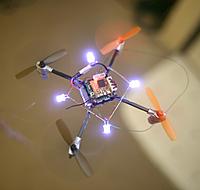
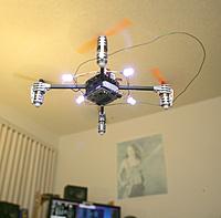
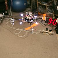
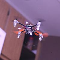
Posted by Jack Crossfire |
Jan 31, 2013 @ 05:13 AM | 9,100 Views
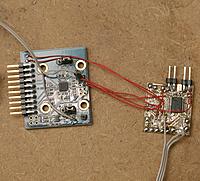
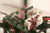
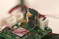
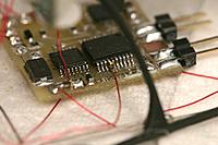
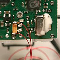
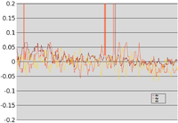
After another heroicly wasted day, the MPU9150 finally surrendered all 9 of its data streams. It has so many problems as a 1st run product, a much improved revision negating all of today's work is guaranteed. But with 2 MPU9150's lying around & a definite use, it was time to bang out a workaround just to get the data from it. The DMP firmware isn't going to happen.
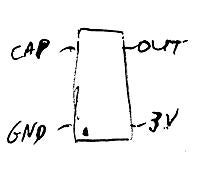
Step 1: the 1st I2C command must be to set PWR_MGMT_1 (0x6b) to 0x01 to move it out of sleep mode & set the clock to the gyro oscillator. That puts 1.8V on the REG_OUT pin & 25V on the CPOUT pin. Nothing else works if it isn't the 1st command.
Step 2: set the remaining configuration registers after PWR_MGMT_1
0x37 = 0 // disable i2c passthrough
0x6a = 0 // disable i2c master
0x1b = 0 // gyro config
0x1c = 0 // accel config
0x19 = 0 // desired sample rate divider
The I2C passthrough didn't work. Physically bonding the mane & aux I2C busses didn't work. Only using dual I2C busses connected to the mane I2C & the aux I2C worked. The mane I2C reads the gyro & accel. The aux I2C reads the mag.
The real problem is if you simply read the gyro & accel registers, you'll always get the same value. They tried & failed to synchronize the register refreshes with inactivity on the I2C bus.
The only way to get the registers to refresh is to issue a bogus command to the mag on the mane I2C bus. I chose to read the mag status register (0x02) 1st on the mane bus to get the gyro/
...Continue Reading
Posted by Jack Crossfire |
Jan 30, 2013 @ 04:13 AM | 8,146 Views
Another round banging on the MPU9150 revealed the accel/gyro part isn't being powered on. The aux SPI pins don't do anything after enabling AUX_SPI_EN. Now the CPOUT pin has been revealed to be 0V. REGOUT is 0.5V. Device ID & register values of the accel/gyro come out properly, but enabling CLK_OUT doesn't do anything. An undocumented register seems required to power it on.
The previous round revealed the magneto part could be read on a direct connection to the aux SPI pins, but there was no data from the accel/gyro.
The Goog revealed a single page where someone found it wouldn't generate an interrupt.
http://www.i2cdevlib.com/tools/analyzer/34 There's no other documented use of it.
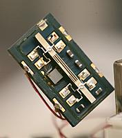
So the Ladybird can't fly on purely the magnetometer. It tilts too much for that to work without a full IMU. The search for a new gyro began with recycling a 7 year old can, the very 1st gyro in the apartment. It conveniently cracked open on the 1st crash, revealing how big it is compared to a modern gyro. It had the needed vibration resistance.
Having a functional gyro made things slightly more stable. Reducing the I terms made things even more stable. It's still changing calibration with every battery change & losing control during most turns.
Posted by Jack Crossfire |
Jan 28, 2013 @ 11:02 PM | 8,371 Views
There was 1 battery change which produced very stable flight with very slow velocity updates on the order of 1/2 second. Yaw was non functional. Only pitch & roll worked. It could have been a lucky compass alignment.
There could be an unknown configuration error during the battery changes, making it unstable. Manual flying is still stable, weeding out the stick voltages. There could be a random delay in the video.
There's also the random heading offset during battery changes. The battery wires are bent differently for each battery. Different current flow inside the battery or different bending of the fuselage can also explain it.
The analog gyro has a huge noise offset when the motor starts, making it completely worthless. It could be the LDO, the Vref, or vibration, but there aren't enough batteries to do any testing or make any conclusions. Those USB chargers take many hours.
Posted by Jack Crossfire |
Jan 28, 2013 @ 04:35 AM | 8,216 Views
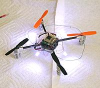
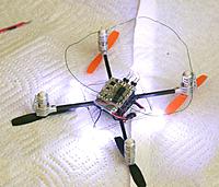
So the Ladybird has been pretty disastrous, certainly the hardest thing for the computer to fly.
Reflowed the LISY300 board again, in the hope that the failures were caused by a flaky solder joint. Soldering has greatly improved, since it was originally reflowed. It's time for some quality time with the MPU9150, but there's hope every last old component can be used. After a few crashes, the soldering does appear to have fixed it.
The soldering iron also does a better job reflowing hot glue than the glue gun, making it flow into the nooks the glue gun can't make it smooth enough to flow into.
Noted getting the Devention 4 to work requires powering up the ladybird & the ground station 1st, then powering up the Devention. The Ladybird has to be powered on so the ground station can go from configuration to PWM packets & send the right stick voltages.
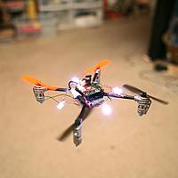
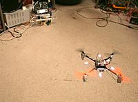
The Ladybird hovers in a single place. Ask it to change position & it goes crazy. Heading is showing extreme instability. Every battery change, the heading offset changes.
The Syma X1 was more stable, as indoor quads go. Making a quad more stable requires much better gyros, like the ADXRS652. That would require a much bigger airframe.
Posted by Jack Crossfire |
Jan 27, 2013 @ 04:55 AM | 8,783 Views
People have mounted wireless cameras on the Ladybird. The webpage describing it is an always down home server, but
http://rcmodelreviews.com/fpvbackpack02.shtml if you're lucky.
Thanks to the masses, we know the camera is probably
http://www.securitycamera2000.com/pr....6mm-Lens.html
& it runs on 3.3V.
The transmitter is
http://www.sdshobby.net/58g-200mw-wi...l#.UQT8OrqVu5M
http://www.foxtechfpv.com/tx5823-200...ers-p-272.html
Complete the set with a 5.8Ghz receiver, MPEG video capture, & Marcy 3 system, & you can make your own autonomous indoor camera. But don't try to sell it because alwaysinnovating.com is squatting on the patent.
http://www.alwaysinnovating.com/products/mecam.htm
It's the most despicable practice to mock up an idea without actually making it work, for the sole purpose of charging a license fee to anyone to makes it work.
The mane problem is shrinking the Marcy 3 board to make room for the camera system. It would definitely need the MPU9150. The Blade MCX is a more practical platform for video, even though it isn't as small.
The Marcy 3 board has lots of problems on the Ladybird, manely a radio usually failing to initialize, a very unstable gyro. It could be 2.4Ghz interference. There isn't much you can do with only 2 batteries, but 1 lucky photo did get in, before the gyro failed.
After the Marcy 3 problems, the Ladybird is extremely unstable compared to the Blade MCX. The thing that made it finally autonomous was increasing
MAX_POSITION_CHANGE, another buried parameter in the vision system. That threw out motions too big to be anything but glitches, but was too small to handle the required motions.
Heading alignment has to be spot on & seems to be another matter of offsetting the heading during calibration.
Posted by Jack Crossfire |
Jan 26, 2013 @ 02:57 AM | 8,108 Views
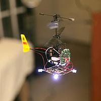
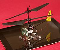
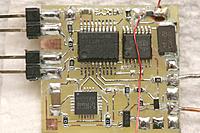
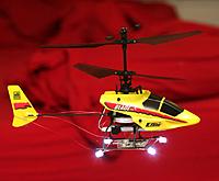
The Ladybird has a stable 3.27V power supply, suitable for a gyro. Its integrated digital IMU is useless for a strapon autopilot. There were once 4 ancient LISY300 gyros in the apartment, ideal for the task. 3 were mounted on boards. 1 is unaccounted for. For a single axis, analog gyros are easy, take a lot less CPU time, & are platform independent.
The LISY300's were the 1st gyros for under $13 & got the 1st etched PC board, back in 2009. Today's equivalent part is the LY330ALH for under $5.
Unfortunately, the Ladybird has great difficulty staying connected. It may be continued grief from the PWM stick voltages. A bag of DACs gets closer.
Posted by Jack Crossfire |
Jan 25, 2013 @ 01:32 AM | 7,793 Views
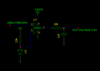
After many hours of heroic soldering, the stick voltages were finally accurate enough to get the ladybird off the ground. 50% needs to be exactly 2.5V. The only way to get the ripple low enough was 10k & 1uF. The sticks now update at only 20hz, but it was the fastest a PWM using the LM324 for level conversion could do it.
The LM324 only goes up to 20khz before it just outputs 0V. It doesn't roll off. It just dies. Overriding stick voltages with the required level conversion, at a decent update rate requires a proper DAC, but overriding the stick voltages isn't considered the final solution.
So a Parallax X-band & Allegro A1302 arrived. The X-band is 1 of those widgets with no obvious purpose that someone somewhere always finds a personal need for. The mane problem with it would be detecting unwanted motion from fans, trees, cars, & the user. Sure enough, the social networks emphasize finding ways to make it more directional.
The mane problem for foot soldiers is not detecting intruders but the IED. It would require a sensor for all types of explosives hidden behind all types of materials in a 30ft range. No effective weapon against the IED has ever been found except human motivation & we all know people fight harder for freedom than individual mandates, grocery bag taxes, runaway inflation, & gun bans. Americans will never win against the armies of capitalism.
There is a bag of hall effect sensors in the apartment from magnetic levitation days. The problem was making the magnetic levitator fast enough to do more than levitate, like shake a fluid. The hall effect sensor maxed out at 20khz. The electromagnet couldn't transition fast enough.
Using a less sensitive sensor allowed heavier objects to be lifted. Using a more sensitive sensor allowed objects to be farther away. The A1302 is about the least sensitive sensor.
Nowadays, magnetic levitators are $40 items. The old levitator doesn't get any attention, anymore.
Posted by Jack Crossfire |
Jan 24, 2013 @ 05:10 AM | 8,204 Views
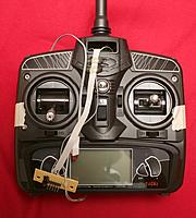
Automating the Ladybird is a big deal since it requires many many voltages, leading to a pile of LM317's on the verge of cracked resistor circuit board incineration. Mercifully, the remote control has reversible directions, eliminating the need to make a new table of stick directions or require multiple steps to initialize the stick voltages.
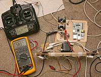
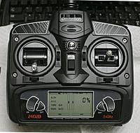
This remote control can be easily reverted to manual control, but it only lasted around 17 seconds on the AA's it came with, requiring a mains power connector. It has a voltage reading 1V lower than the true battery voltage.
Posted by Jack Crossfire |
Jan 23, 2013 @ 03:19 AM | 8,165 Views
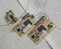
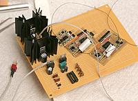
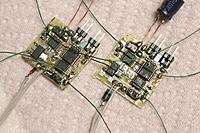
definitely gets tedious. It's taking around 1 week to fabricate each camera station. It's nearing the point where prefabricated boards with solder paste & hot air reflow would be a better deal than etching at home & hand soldering.
Posted by Jack Crossfire |
Jan 21, 2013 @ 07:30 PM | 8,150 Views
Looking at the videos of the AR Drone 2.0,
they've taken the time honored system of downward facing optical flow & sonar to new levels. Multicolored squares on the floor not only allow it to localize to an absolute position, but do it precisely enough to reproduce vicon performance.
The cameras are undoubtedly fast, over 60fps, & high resolution. There's no english information on the sensors, just about replacing them. If you want to know how it works, learn chinese.
They probably get some position information from the accelerometer, but Arducopter only gets position information from the accelerometer at 2Hz.
The floor patterns for localization wouldn't work in the apartment, since there's no empty floor space.
Tethered copters
Are harder than you think. The 5ft cable it would take to make a Blade MCX tethered has 1ohm of resistance. It would need 5V to run the motor at 4V, but have to drop to 4V as soon as the motor stopped. So a truly useful tether needs a current shunt resistor & a very fast, variable power supply to make sure the voltage at the copter is always 4V. The ground voltage could be 4V-30V, depending on cable length & current.
Posted by Jack Crossfire |
Jan 21, 2013 @ 03:02 AM | 7,578 Views
In the next round of the battle for RF propagation delay measurement, 2 radio repeaters were built. They simply had 2 radios connected as closely as possible, reflecting a signal. An oscilloscope measured the round trip time of the signal. Once again, measuring RF propagation delay failed. It seemed the automatic gain control in the radios influenced the arrival time more than the distance.
1us of phase shift happened just from changing antenna direction. They would have to be 300 meters apart for phase due to distance to appear.
The received signal on the MRF49XA is delayed by around 6us of filtering or the minimum period of a waveform it can transmit, which makes a single pulse useless for measuring propagation delay. You need a waveform at the radio's maximum bandwidth, so the phase of 2 overlapping waves can be measured.
The highest frequency gotten out of the MRF49XA was 128khz on the RCLKOUT/FCAP/FINT pin. That would support a UART running at 256kbit. Any higher & it started dropping bits. It was disappointing not to have any overclocking ability.
Having a transmitter & receiver on different frequencies next to each other did not cause interference as feared. That happened in a 2010 diversity experiment using XBees.
It takes some voodoo analog magic to measure propagation delay & carrier phase. If a 256kbit radio has 300 meters of jitter, a 2Mbit radio would probably only resolve down to 40 meters at most.
Posted by Jack Crossfire |
Jan 19, 2013 @ 02:26 AM | 8,090 Views
So you wanna get wireless digital video from the smallest package.
The MRF49XA/SI4421 have been the workhorses for the last 4 years. They send 256kbit at 1mW.
In 2010, the MRF89XA came out. It sends 200kbit at 30mW & has a bigger package.
$parkfun has had the nRFL01+ since 2009. It sends 2Mbit at 1mW. It doesn't have a baseband pin like the MRF's, so getting 2Mbit requires a lot of CPU time.
All the RC products use Cypress. Nothing from Cypress or TI has a baseband pin, but there are single chip options for over 1Mbit.
The $10 ML2730 has baseband pins, 2Mbit, & puts out 100mW. 4 of those might be a useful position sensing solution for $40. It could handle video & not have the dropout problems or latency of wifi.
That's about it, in the chip radio department. The fake test pilot's 2009 decision to go with the MRF49XA was driven by the need to avoid analog 2.4Ghz video interference & cost, but now that digital video is the priority, the ML2730 may be the chip of choice.
The baseband pin potentially allows distance to be measured & allows data to be sent with much less CPU time. Just connect the baseband pin to the UART instead of banging on SPI registers. The 256kbit chips would probably only resolve distance to several meters but a 2Mbit chip might do the job, indoors.
256kbit would probably send a compressed 160x120 JPEG at 1 frame every 4 revolutions. 2Mbit would do each revolution. 160x120 is about the highest useful resolution when the current camera is on a monocopter. The wifi & bluetooth solutions are all heavier & interfere with I2C.
dBm is a very confusing metric. We all know how far 100mW can go, but not 15dBm. The easiest way to convert dBm to practical experience is the 2nd digit being the number of 0's. 0dBm = 1mW 10dBm = 10mW 20dBm = 100mW 30dBm = 1000mW
Posted by Jack Crossfire |
Jan 18, 2013 @ 01:13 AM | 7,719 Views
The Blade MCX being the most stable indoor flying thing ever invented buys most of the precision, but it still took some doing to get vision, sensors, & feedback good enough to keep it in the smallest box. The Blade MCX is 4 years old, but it had just the right combination of cyclic, flybar, & servos to be more stable than anything since.
The IMUs since then haven't achieved the same motion damping of the mechanical flybar. It's a mystery why the Blade CX2 wasn't as stable.
Posted by Jack Crossfire |
Jan 17, 2013 @ 06:00 AM | 8,089 Views
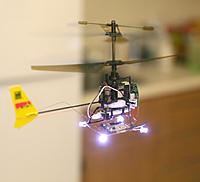
That there is the widowmaker, a very special prototype with some changes that were unlikely to work but ended up making it super stable. Manely, tapping the Blade MCX's integrated gyro to drastically improve the heading detection without increasing the component count.
Its heading is extremely stable, probably allowing its position tracking to be more stable than using the magnetometer alone. The improvement costs nothing, but would require more parts on copters with no analog gyro already installed.
Another discovery with this system was pointing it 45' left of the cameras during calibration seems to be the optimum alignment for the cyclic phasing. It may be specific to this copter or it may apply to all of them. Even though the Blade MCX is over 4 years old, it seems to continue experiencing subtle design changes, maybe even cyclic phasing changes in the firmware.
Posted by Jack Crossfire |
Jan 16, 2013 @ 01:49 AM | 8,127 Views
So basically, the MPU9150 has an LDO regulator on it, but still needs a more stable voltage than this board has. It wouldn't be the 1st chip to have a minimum stability for I2C to work. Other Invensense gyro flying things have either an LDO regulator or charge pump reducing the single cell to 3.3V. Ancient analog gyros also fluctuate with voltage changes.
So far, these micro copters have proven the smallest indoor autopilot works, but what you want is a flying camera. Dreams of useful quality video from a monocopter were busted. The available cameras aren't fast enough. There were signs that they could be synchronized to the rotation by pausing the clock. The blurry images would then require a really fast wireless connection.
A camera on a micro copter would take serious investment in really fast, microscopic, wireless communication. All roads are leading not to building aircraft, but perfecting a camera & wireless communication.
Posted by Jack Crossfire |
Jan 14, 2013 @ 09:53 PM | 7,762 Views
Building up 4 of these over the months is a good lesson in what's paying off US's debts: the treasury debt, trade deficit, mortgage debt, federal reserve balance sheet, & entitlement programs all totaling some $100 trillion. It's all being paid by Chinese spending all day building up autonomous Blade MCXs.
US's $100 trillion of debts are being paid off by a lot of tedious, monotonous, mind numbing work which makes the thousands of times you have to retype your password to do anything on iOS seem like a vacation. You can feel every $100 billion. Every stock market trade, credit card plan, house flip, advertizing revenue stream, service plan that milks additional value out of the original product is still based on the 1 piece of manufacturing.
There would be no way to mass produce a UAV with this much intricate fabrication in your apartment. It takes around 16 hours to produce each one. 16 hours of rent alone is more than they can sell for. Yet through the magic of tooling & mass production, Chinese with no lives pull it off, every year, servicing all of US's debts as well as feeding themselves.
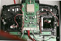
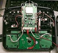
Looking inside the Ladybird's Walkera control, it's quite a substantial piece of kit for $50. There are a lot of hand routed wires. The pots go from 0-5V. The batteries don't last very long. It would take some doing to override.
With the current state of cheap vision systems pretty well maximized, the next step is using a more substantial IMU. A bare magnetometer is enough to get the job done & get pretty tight hovering, but turn towards the right angles & it gets real wobbly.
A full IMU is required to get the next level in precision. That requires a stable 3.3V voltage & a more powerful microcontroller, which takes some doing in a microscopic single cell indoor copter. It might require completely replacing the stock electronics.
Posted by Jack Crossfire |
Jan 14, 2013 @ 01:09 AM | 7,710 Views
Got the last of the features on the tablet which were last done on the RC transmitter, years ago. Manely manual position control in autopilot mode. Rediscovered the ages old problem where velocity & direction can't be changed if a move is already in progress. It would have to stop moving & recalculate a new starting position of a new line to fly.
It was all part of a plan to make it fly in straight lines. Merely setting fixed velocities didn't make it fly in a straight line. It would need a much larger flying area for changing velocity to be practical. The war on straight lines was a long battle in 2008, comprising many blog posts.
As the tablet interface evolves, it's very confusing, with separate inputs for manual mode & autopilot mode.
There is a desire to do the same manual control with the monocopter & the ladybird, convert something big enough to fly a camera.
Posted by Jack Crossfire |
Jan 12, 2013 @ 05:58 AM | 7,843 Views
Many years ago, a fake test pilot noted that averaged sensor data produced better flying than lowpass filtered sensor data. Lowpass filtering was the academic way of treating the data because it got rid of aliases.
The fake test pilot also noted that jittery servos produced better flying than perfectly timed servos.
In all these cases, the noisy unfiltered data had less latency than the filtered data & glitching the servo PWM around 50hz conveyed more data than their normal 50Hz update rate allowed. Since there were no data points at an alias frequency & with enough amplitude which could cause the aircraft to oscillate, the reduction in latency was a bigger win than the reduction in noise.
Now a camera system has 2 cameras, each running at 68fps, limited by clockcycles. They're not perfectly timed or synchronized, so an image from either camera is captured at 136 unique points in time. A new position is calculated when each of the 136 frames comes in. This allows slightly faster position updating than if the cameras shot at exactly the same 68 points in time, without requiring more horsepower.
The velocity calculation has only a 1/13 second delay, is pure noise, but gives a much tighter flight.
Anyways, the dual 68fps system uses 90% of the raspberry pi. The RLE compression generated by the board cams takes a lot less horsepower to decompress, but is made up for in the higher framerate.
Posted by Jack Crossfire |
Jan 11, 2013 @ 03:24 AM | 7,715 Views
An 0402 resistor cracked, instantly frying $50 of electronics & 1 day. So it was once again Wednesday with a camera needing calibration. Fortunately, the crack was detected here instead of in the field.
The mane problem with the LM317 is if 1 right resistor cracks, it runs away at full power. It was always expected to happen. Tear down some camera mounts, bend some boards while undoing the glue, crack the right resistor, & 1 day is gone. Many SMD resistors have cracked over the years, but never the right one until now.
Eventually, everything made it back into the air, using the dual camera turret. The framerate is now 70fps. Flight time increased to 3m30s from 2m. Navigation can potentially be tighter, but there probably won't be enough time for optimization.
Posted by Jack Crossfire |
Jan 09, 2013 @ 10:58 PM | 7,852 Views
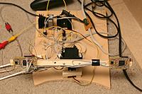
The problem became obvious, immediately after starting the calibration. The pointing direction of the servos can't be known precisely enough to get a distance from the angles of the cameras. The convergence angle needs to be more precisely known than any other angle to get a useful distance.
The cameras in a 2 eye mount have a fixed convergence which can be hard coded. The cameras in 1 eye per mount have variable convergence which must be deduced from the servo angles. That couldn't be known as accurately as hoped. The Hitec HS-311 is the tightest servo known, but it's still not accurate enough.
If the cameras were on different sides of the room, so they always converged at 90 degrees, the problem would be solved, but that would require having a 270 degree field of view with no lights that could interfere with machine vision. The cameras have to be close together & on the same side of the room to make the lighting practical.
Time to tear down another experiment & build a 3rd dual eye mount.
 Views: 236
  Views: 213
  Views: 214
  Views: 226
  Views: 212


