--Oz--'s blog View Details
Posted by --Oz-- | Feb 04, 2023 @ 01:16 AM | 7,548 Views
...
Posted by --Oz-- | Nov 29, 2021 @ 02:28 AM | 27,220 Views
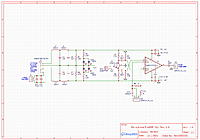
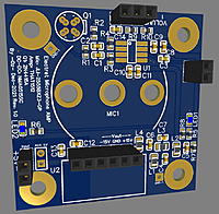
I came across a YT video on how to build a good quality microphone for low cost. He does a nice job on the mic and the circuit I figured could be updated for better performance .

Building a quality USB-C microphone (23 min 34 sec)


I thought of a few improvements:
Low noise is one of the keys to a good mic as you know. Many different paths for noise to enter and different ways to minimize the noise and some other improvements.

Filtering:
1. DCDC converter:
I don't see the need for the big RC filter (100Ω + 2200uF) with huge size electrolytic caps. The dcdc converter only has 33mA max output and the circuit current draw is very little. More importantly is low voltage ripple (from getting into the signal through the supply rails). The dcdc converter is running at 90KHz, that is the target freq needed to reduce ripple voltage. As a minimum a LC filter of 220uH and 1uF would be recommended. In effort to reduce voltage ripple even more, adding a second LC (making a PI filter) is one option. This should do much better for filtering noise from the switching boost converter and USB supply. For the input dcdc rail, low esr (X7R or X5R) 0.1uF and 22uF ceramic caps should be added.

2. IC Amp filtering:
I would add caps placed as close as possible to the IC power pins. A low esr (X7R or X5R) 0.1uF + 1uF ceramic caps on each rail (pin #4 and #7).

3. Max capacitance: The dcdc converter datasheet shows "the maximum recommended output capacitance is 10...Continue Reading
Posted by --Oz-- | Apr 11, 2021 @ 05:06 PM | 11,034 Views
This thread is about different ways to control a brushless motor, the pros and cons of the different ways to drive brushless motors.

I have a stack of old hard disk drives. The neo magnets are very strong, the head spindle and motor bearings are amazing with zero slop. Controlling the three phase brushless motor is not simply hooking up power wires and it spins like a brush motor does. About 3 years ago I had the idea to drive a brushless motor with a single fet and square wave generator and it works, but with limitations.

I currently have played with these brushless motor drive methods:
A: Single fet and function generator driving the motor.
B: H-Bridge and function generator driving the motor.
C: Using 3 fets, 3 resistor and three caps in a cascade fashion
D: Using 3 fets, a decade counter (4017 setup for 3 count) and a function generator.
E: RC electronic speed control (ESC) driving all three phases, with a servo tester to control the esc.

A: Single fet and square wave generator driving the motors 2 phases
(phase-1 to +supply, phase-2 to fet and then ground). Current only goes one direction.
Pro: Very low cost.
Con: Slow accelerating, decelerating and torque.

B: H-Bridge and square wave generator driving the motor 2 phases.
(phase-1 to +supply, phase-2 to fet and then ground). Current goes both directions.
Pro: Very low cost. (few bucks)
Con: Slow accelerating and decelerating but better than method A.

C: Using 3 fets, 3 resistors and...Continue Reading
Posted by --Oz-- | Mar 10, 2021 @ 10:02 PM | 19,199 Views
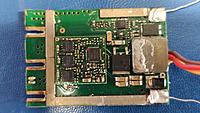
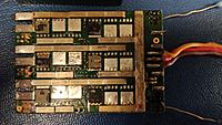
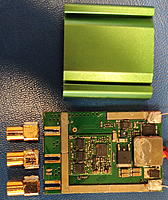
I was given this ESC after a crash at the field, when it was given to me the heatsink was gone, a third of the fets was shorted or ripped in two and missing the input caps. After some troubleshooting, it turns out, there was just 6 good fets of the 18, the minimum requirement to get working, after moving the good fets around I now have it working on the bench (no heatsink and reduced power).

Still not knowing what model ESC it was, after searching a bit, it looks closest to a Castle Talon 90A, makes sense for several reasons, 3 fets @ 60A=180A then reduce for thermal reasons and 90A sounds about right, the 5.5mm connectors , the beeps from the motor sound like a castle (from watching YT videos), the led's are in the right place and the huge BEC inside (castle claims 9A cont and 20A peak, and it looks like it). It was recommended to plug in a USB castle link and I borrowed the CC linker and its a Talon 90A.

I ran the esc for two hours at ~10% thro on a little 2826-2200kv motor w/o prop, and it is still working. The stock fet TPH9003NL ($7 for qty=20) is 30V 60A 9mΩ , I found some better fets, the TPH4R50ANH ($12 for qty=20), 100V 60A 3.5mΩ, roughly one third the resistance. I might convert this esc to 12S (changing some caps/resistor values), if nothing else it should run cooler with the much lower RDSon (resistance) FETs.

After the third hour running on bench, it stopped, another FET died, more than likely that FET was wounded. So I removed all fets and now my temporary test setup with external fets (using irzf48n 60V 50A to-220 package). I have run this setup for about 12 hours w/o issues, so I bought the one third resistance fets (60A 100V), will update when they get here and install them.

Question, is there a lower cost option for CC USB link dongle (I use the $2 arduino nanov3 for all my BLHeli_S/_32 ESC, or the passthrough feature of the flight controller), I dont want to spend $20 on CC linker?

~

Posted by --Oz-- | Feb 11, 2021 @ 01:20 PM | 17,051 Views
~~~
Posted by --Oz-- | Jan 20, 2021 @ 02:15 PM | 17,030 Views
I wanted to be able to control the brightness of some LEDs from Ardupilot flight controller.
I wanted 0 to 100% pwm output from the FC pin to drive the gate of a FET, then you can control anything (LEDs/motors/solenoid/etc), but Ardupilot does not have that function.

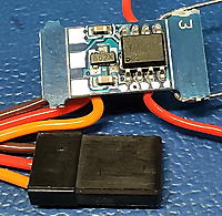
Ardupilot has servo passthrough function, it passes a RC channel from the Rx through the FC to a output pin. This will require a brushed motor esc, most of them are larger than the size of the FC, and fitting them on a 5" quad is a bad choice. Then I found on AliExpress for $3 shipped, a servo motor esc (for continuous rotation servos).

I got one and have tested it on the bench, its got some issues that I was not expecting.
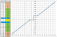
1. Most Tx/Rx will not output below 1000us and above 2000us, this means you will maximum get +/- 70% speed (see picture).
2. Lowest PWM output is 17.5%
3. Maximum 6V. Maybe possible to modify for more voltage by cutting the FET driver supply trace and feeding more voltage, but I have not found the datasheet to the FZMOS-5X (so-8 package).

Large zero thro dead band 1390 to 1591 (200us)
See the attached picture for the PWM info.

So with the limitations of 6v, 1A, 17% to 70% max output, it will work out of the bag and its low cost and tiny.

AliExpress INFO:
1pcs DIY Dual-way 1A Mini ESC 5V DC Brushed Speed Controller Module Winch Control Bidirectional Driven Circuit Board for DIY RC Part
https://www.aliexpress.com/item/1005...36e34c4duQeMF3
Specification:
- Size:...Continue Reading
Posted by --Oz-- | Apr 30, 2020 @ 12:46 AM | 21,777 Views
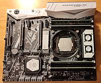
I been a PC gamer since the early 80's, yep, a clone of the IBM XT, never bought a prebuilt PC till 5 years ago (for my mom). In the last decade I built a couple i5, i7 and have enjoyed them.

Then I came across this video, 8core cpu for $53 and comparing it to the i9-9900K ($500 cpu) with a very nice 5700 video card, it opened my eyes at used server cpu's. You really need to see the results comparing a old used server xeon to a new cpu.
8 Core CPU for $53....!? Will it BOTTLENECK a RX 5700 XT...!? (16 min 9 sec)


I learned a few things,
1. Used Xeon server cpus are low cost, high preformance,
2. chinese mfg have developed motherboards for server cpu with pc atx form factor
3. video games are mostly limited by the video card (relativity)

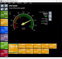
That video led me to Aliexpress.com, been there with about 40 purchases for DIY electronics items, but being new to xeon server cpu's I was lost compared to desktop cpu's. I did some searching and found Passmark cpu benchmarking and this russian website (google translates it very well), the guy that runs it is good, he loves bang for buck and tells you how it is. Seems quite a few YT reviewer use his info.

Check out the russian website, across the top is the sockets, look at the better sockets, the 2011 and 2011-3,
https://xeon-e5450.ru/
the xeon build part is good comparing different builds/price
https://xeon-e5450.ru/faq-po-sborkam-na-xeon/

Here is the Passmark website, I started using them from last December,...Continue Reading
Posted by --Oz-- | May 21, 2019 @ 12:05 AM | 18,811 Views
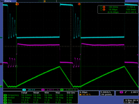
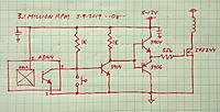
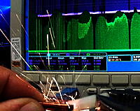
Look at the picture, this picture is amazing once you figure out what happened. The "T" in the top left of the picture is the scope trigger point, ball at rest (0 rpm) 25ms later, the ball is at 3.2 million rpm!
Name: 0rpm to 3.2Mrpm in 25ms - 250W.jpg
Views: 203
Size: 345.2 KB
Description:

EDIT: Here is 0 to 3.4 million RPM in 15ms, thats an average of 227,000 RPM per 1ms (0.001 second)!
Name: 0 to 3.4 Mrpm in 15ms.png
Views: 113
Size: 2.72 MB
Description:

EDIT: Here is 0 to 2.1 million RPM in 1ms (0.001 second)!
In 20 pulses, it does 0 to 2.1 million plus rpm, 20V, 16Arms (320W) to spin a 0,1g ball
Some math:
1 revolution = 27.65us,
36,170 revolutions per second,
2,170,000 rpm
...Continue Reading
Posted by --Oz-- | Apr 23, 2019 @ 12:50 AM | 21,510 Views
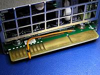
I bought a couple of these for $27 shipped on ebay, turns out they were different than the three I already have working (DPS-800GB). Different connector, so I needed to figure out how to turn them on.

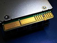
As can be seen in the pictures, the 5th pad on top and bottom need to be shorted to ground and the supply turn on. The big pad closest to the edge is ground on top and bottom, of course next to it is 12V.

-------------------------
INFO on how to turn on the DPS-1200FB-1 PSU
To turn on, simply connect pins 36 and 33 with a resistor of 500Ω or less, even a short is fine.

Today I played with my pair of DPS-1200FB-1 PSU. So I tried a 1K resistor, it would not turn on, then a 750Ω (the two most common resistances I found people using in my search last night), same, nothing out the main output. Then I grabbed my resistor decade box and connected up with a ammeter.

Open 3.1v 0mA
1k 0.58v 0.5mA
800 0.54v 0.57mA
600 0.34v 0.57mA
500 0.29v 0.59mA
200 0.12v 0.62mA
100 0.06v 0.63mA
0 0.001v 0.65mA

My two power supplies turn on at 500Ω or lower, indicating it needs under 0.3v to trigger the turn on. As can be seen there is very low power and a wire works fine.

When the main output is off, the 12V standby (SB) and the 5V output(s) on the bottom of the connector are on.
----------------------------
Sticky:

1,000,000+ rpm

Posted by --Oz-- | Mar 15, 2019 @ 11:15 AM | 22,753 Views
3.8 Million RPM 1338mph 2153kph 24.3 Million Gs (2 min 43 sec)

12-31-2020 My new video using a completely new circuit, fets, sensors and smaller balls. A lot of info in the video description.
PMBO 2020 By -Oz- 2 Million RPM (3 min 4 sec)
...Continue Reading
Posted by --Oz-- | Feb 13, 2019 @ 10:40 PM | 22,674 Views
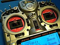
I bought the M9-R on sale for $34 a pair 6 months ago, I just couldn't pass them up. Even though I did self modded hall gimbals in Jul 2016 and still work perfect, around 20K flights on them.

I wanted to use the short throw on the thro and modify the other gimbal back to normal 60 degree throw, also they will match color. After collecting dust for 6 months, in a couple of minutes looking at it, bingo, simply add four 1.5mm washers under the red ALU plate (see picture), now it has the stock ~60 degree travel like the stock gimbal has.

I took some OTX raw data and photos to compare travel degrees of all four axis. Looks like the raw travel numbers are within reason of the other axis (AIL and YAW) movements (+/-~100). These numbers have a lot to do with how close the sensor is to the magnet (closer gives larger range).

I took some pictures to compare my 1.5mm washer mod to see how close it is to 60 degrees. Roughly its ~1.5 degrees less than the other two axis (AIL & YAW). Of course there is some error in my measurements. I am pretty happy with a first try with 1.5mm thick washer guess.

I did the heat shrink tubing over the thro drag bar and a dab of rc car diff grease, this thro gimbal now feel as smooth as anything I have felt. So far pretty happy with them.