grmis's blog View Details
Posted by grmis | Jul 11, 2019 @ 03:53 PM | 8,537 Views
Hi !

Here is my new wing for FPV: a Zohd Dart (635mm wingspan), made by Sonicmodel.
Posted by grmis | Nov 07, 2018 @ 04:01 PM | 7,205 Views
Hi.

Here is my first build of an RC boat. It is a wooden kit of a fishing boat (Thonier) made by the French hobby company 'Soclaine'. This kit seems to date back to 199x, but it can still be found in several online French  shops. I got mine on a flea market, but it was completely new, the box had not even been opened. It is for my 10 years old son.

http://www.soclaine.com
Posted by grmis | Jul 19, 2018 @ 08:41 AM | 8,078 Views
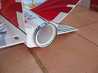
This is my (second) EDF jet. It now has about 40 flights, and I recentlty installed a flight controller in it. So it is perhaps time to post here a few lines and a few pictures about it.

Setup:
- Stock motor, ESC and fan
- Turnigy 4S/3000mAh/30-40C Lipo
- Home made after-burner LEDs, with Arduino and programmable RGB leds (see here for details)
- Flight controller: Omnibus F4 v5, with iNav 1.9.
(PWM1: ESC; PWM2: unused; PWM3: Aileron1; PWM4:Aileron2; PWM5: Elevator; PWM6: AfertBurner module; UART6: SBus; UART3-TX: uninverted SmartPort; UART1: GPS(future)). In case someone is interested by the detailed parameters (PID etc), I attached my configuration (“dump”). The stabilization (“angle” mode or “acro” mode) is quite useful when launching the plane, and also for landing. I can now land by glidind "hand off" in angle mode !
- Radio: FrSky XSR receiver (connected to the FC via SBus & SmartPort telemetry). Taranis X9D programmed with 3 flight modes (Manual/Acro/Angle) and flaperons (via iNav servo mixer and 2 AUXchannels).
- To be added soon (done): GPS, to get the speed (via telemetry).
Posted by grmis | Apr 02, 2017 @ 04:35 PM | 20,176 Views
Hi,

I have put some led ring on my FMS Super Scorpion EDF jet, for an afterburner effect. I took a flexible strip made with individually addressable LEDS (WS2812B 5050 RGB, also called NeoPixel). The price is about 14 euros on eBay, for 1 meter with 144 leds. For a 70mm fan, only ~35 leds are needed (the strip can be cut at the desired length).

An Arduino pro mini is controlling the LEDs (using the Adafruit_NeoPixel library). It reads the throttle channel (PWM signal, from the receiver) to vary the intensity and the color or the leds. I tried to make it more ‘realistic’, by including some slight (random) inhomogeneities along the ring, and some ‘flicker’ at high throttle. As for the color, it color goes from red, yellow, to blueish. This can of course be customized at will, by changing a few parameters. The Arduino code is available here:
https://github.com/grmis-fr/NeoPixelAfterBurner

Since each led can draw up to 60mA (under 5volts), the total current can exceed 1 amp, and this may be too much for some BEC. So, I am powering the arduino and the leds using a small adjustable step-down switching regulator (type mini-360). In my case the lipo is 4S. This small buck converter could work with 5S too, but not 6S (it would exceed the max voltage of the mini-360).

Ok, now comes the negative point: the luminosity is a bit too low, and the leds are barely visible if you are flying a sunny day I am going to change the colors a little bit in the code,...Continue Reading
Posted by grmis | Feb 23, 2017 @ 03:52 PM | 31,112 Views
Here is some project that I have recently started : a video diversity system, *without RSSI*.

This this system monitors and compares the video quality of the composite video signals, and switches to the best one. Of course the idea is not new: see for instance the Oracle diversity or the Eagletree ground-station. But the present one is meant to be DIY.

Compared to the popular RSSI-based systems, the advantages a video-based diversity are :
- No need to open the receivers to get the RSSI [Receiver Signal Strength indication] signals. You just have to plug in your different receivers, and they can be of different types.
- There is no need to calibrate the RSSi signals of the different receivers (this is often the tricky part).
- It is also frequent to get a strongly distorted image, while the RSSI is high.
- When the reception level is low (flying far for instance), some receivers have RSSI close to zero, although the image is still viewable. In that case an RSSI-based system is not really efficient.

So far I only tested the system on the bench (video soon : see the post below). I just made some basic indoor tests with 3 receivers in the 0.9G band, and it seems to pick
the best image reasonably well. Of course I still have to test it in real conditions.

A few comments on the hardware:

- Cheap (<20$)
- Some LM1881 chips are used to extract the (horizontal) sync. information from the composite video signal, as in Oracle's system.
-...Continue Reading
Posted by grmis | Feb 21, 2017 @ 01:37 PM | 11,157 Views
Hi,

Here is a simple way to connect a buddy trainer radio, without cable.
One needs:
- a standard receiver, bound to the student's transmitter
- a PPM encoder (look for 'PPM Encoder' on eBay: less than 5 $, shipped from China).
- a BEC (provides 5volts for the receiver & encoder)
- A small LiPo (2S or 3S for instance)
- The appropriate connector to connect to the master transmitter (example: a simple audio jack for JR/Spektrum)

Note 1: This should work with any brand of transmitter, not necessarily the same on the master & student sides. If the channels are not in the right order, just swap some wires between the receiver's outputs and the encoder's inputs.

Note 2: if you have a receiver with a PPM output, then, in principle, the encoder is not required. However, there would be no physical way to adjust the channel order (but maybe one of the two transmitters is sophisticated enough, so that one could change the channel order at the software level).


G.
Posted by grmis | Oct 16, 2016 @ 03:45 PM | 11,775 Views
Hello,

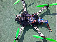
I haven't posted anything in this blog for a long time... So, here is a brief presentation (and some pictures) of my quad racer:

- Frame: zmr 250 (BG)
- Power Distribution Board: Diatone ZMR250 V2.1 PCB Board (BG)
- 5v power( for the OSD and the flight controller): I removed the linear regulator present on the PDB above (too hot...) and installed a small step-down switching regulator.
- Motors: Sunnysky X2204S Ⅱ 2300KV
- ESC: FVT Little Bee 20 amps (BLHeli & OPTO) (BG)
- Flight controller: Racing F3 - Deluxe 10DOF (with baro. & magnetometer) (BG)
- Software: Cleanflight. Some day I'd like to try iNav with a GPS... iNav 1.6.1
- Vtx: Quanum Elite X50-2 200mw, 40 Ch. (HK)
- Antenna: Aomway 5.8GHz FPV 4 Leaf Clover (BG)
- Camera: Sony 600TVL with 2.8mm lens
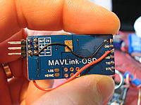
- OSD: Micro MinimOSD (BG)
- Radio RX: FrSky D4R-II (HK).
- LiPo: Nano-tech 1500mAh 3S (HK)
- Propellers: Gemfan 5030 (BG & HK). The motors and the ESC can handle larger props, and/or higher pitch. So I may try soon...

NB: Almost everything was bought from Banggood (BG) or Hobbyking (KH)...Continue Reading
Posted by grmis | Jun 18, 2016 @ 03:17 PM | 17,766 Views
Hi,

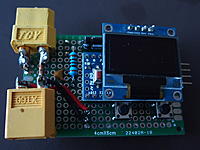
Here is a simple system to measure current, voltage, power and mAh. It is based on an Arduino, a (Hall effect) current sensor (Allegro ACS755-50 or ACS758-50), and an OLED display (using the SSD1306 driver).

This sensor can measure current up to 50 A, but it will not be destroyed if you exceed this value (the datasheet says 200A max.). I give an example of code below, but it is of course easy to customize for your needs (averaging, total energy, battery internal resistance...). One can also use a different sensor if you want to measure smaller currents with a higher precision.

If you find this useful, or if you have some question, do not hesitate to post a message here !

G.

Here is the Arduino code :
Code:
// ================================================
// Author: GRMIS on RCGROUPS
// GrMis@free.fr
// June 2016
// ================================================
// I2C OLED DISPLAY: SCL = A5  ,  SDA = A4
#include <Wire.h>
#include <Adafruit_GFX.h>
#include <Adafruit_SSD1306.h>
#define OLED_RESET 4
Adafruit_SSD1306 display(OLED_RESET);
// ================================================
//Timing variables:
int now,previous_screen,previous_measure;

//Analog input connected to the current sensor
const int ACS755_pin=A0;
//Analog input connected to the voltage divider
const int volt_pin=A1;

//Button pin (to reset the min/max values)
const int Button1=2;

int Offset;
float current;
float voltage;
float
...Continue Reading
Posted by grmis | Feb 21, 2015 @ 05:50 PM | 16,777 Views
Hi,

Here is my new bird:

- Maxi Swift wing, 1m38 / 54 inches wingspan
- Arduflyer board (clone of APM 2.5) with Arduplane 3.2 software + Neo6M GPS
- Turnigy Aerodrive xp C3542/1250kV & 10x6 CAM folding prop
- ESC: Plush 60A
- Two 2200mAh 3S lipo in parallel
- Servos: Hitec HS-82MG
Total weight < 1200g

The first flight was... today :-) So far I only tried the manual & stabilize modes. I will soon try the more advanced modes: FBWA, AUTOTUNE, LOITER, RTL, ...

I am also planning to add several things: 3DR radio, current sensor, camera & video TX, minim OSD and airspeed sensor [Done!]. Of course I will update this blog !

EDIT on June 2017: Now the wing is equipped for FPV:

- pan-tilt camera mount
- 900Mhz/200mW videoTX (+inverted vee antenna)
- MinimOSD [hidden under the red cover, with the FrSky RX]
- Airspeed sensor (Pitot tube)
- LC filter on the power lines to the camera & vTX
- 3DR radio modem (for tuning only, removed for regular flights)
- Max speed in level flight ~100km/h....Continue Reading
Posted by grmis | Jul 02, 2014 @ 04:21 AM | 31,205 Views
This is a simple DIY vibration-meter. It measures the amount of vibration on your machine (multirotor, etc.) and can help balancing your propellers, your motor, or to test the efficiency of some damping system, for instance.

It is based on a cheap analog 3-axis accelerometer breakout (with MMA7361 chip), an Arduino and an I2C-LCD display. The schematics is very simple, no external component is needed. I used an Arduino Nano, but an Arduino pro-mini or Uno (5v/16MHz) would work too.

The Arduino code performs some filtering in order to keep only the oscillating part (above a few Hz). NB: the associated time constant, c1 and c2 can be channged if needed. The LCD displays the amplitude of the oscillations/vibrations, in g.

When the system is "at rest", it show values around 0.009, which corresponds to some "noise" (from the sensor and/or the ADC). As soon as you gently hit the table you will see values around 0.02. So it seems quite sensitive. When stuck on a poorly equilibrated multi-rotor arm you will find values arounf 0.5, or worse.
One could of course use a more accurate digital accelerometer, but the analog MMA7361 is enough for the kind of vibration analysis I had in mind, and
the breakout board costs less than 2 euros (shipped from China) on eBay.

Remark: By shaking it vigorously you can switch on and off the LCD backlight (a trick to avoid putting a button)

The accelerometer sensor is quite light, so it can be taped on the system you want to...Continue Reading
Posted by grmis | Mar 26, 2014 @ 10:42 AM | 17,232 Views
Hi.
My (first!) FPV quad is now flying relatively well, so let me present its detailed configuration. Comments or questions are welcome !


Frame: SK450 + dead cat conversion (Hobbyking). I did not used any distribution board -- power cables are just soldered together.
Motors: Sunnysky 2212 980kv (eBay)
Props: Gemfam plastic 10*4.5 (eBay) EDIT: now carbon 9*5.5 (from HK, see pictures a few posts below)
ESC: F30A (Hobbyking) flashed with SimonK firmware (I used the KKMulticopter Flashtool).
Lipo: Turnigy 2200 mAh 3S. Update (Sept. 2016): Now flying with two lipos in parallel, for longer flight time with the HD camera and the brushless gimbal.

Flight controller:
- Crius AIO v1 [clone from Hobbyking in fact]
- Software: MegapirateNG 3.01 R2. http://www.megapirateng.com/
- GPS: uBlox Neo-6 (Hobbyking). Update (Sept. 2016) : uBlox M8N (now ~16 sats. on average)
- Working modes: STAB / ALT-HOLD / LOITER / RTL. EDIT: + RTL on failsafe [I can turn off the radio in flight!]
- Installed on a "vibration absorbing" mount with 50g balls (Hobbyking). Doing so turned out to be crucial to have a descent alt-hold.
Radio link & telemetry:
- FrSky, D4R2-II receiver in PPM sum mode (->single cable to flight controller).
- PWM analog RSSI output of D4R-II is connected to the flight controller (input A2) via low-pass filter (5kOhms+10uF). Thanks to this, the radio RSSI is visible in the goggles. This is nice to be sure I do not screen the transmitter
...Continue Reading
Posted by grmis | Jan 09, 2014 @ 08:24 AM | 21,948 Views
Since I have some trouble to set up the governor mode of my YEP-40A ESC... I thought that it would be nice to build a cheap & simple RPM (headspeed)-meter for my HK450 heli, using the FrSky telemetry [D4R-II receiver & FLD-02 display, but without the FrSky sensor hub]. This has probably be done by someone else before (?), but let me detail how it works anyway.

A tiny neodymium magnet is glued into a hole drilled in the auto-rotation gear. The passing of the magnet is probed by a Hall effect sensor [ref: A3144, 10 for less than 3$ on ebay].

The output of the the Hall sensor is connected to a digital input D3 of an Arduino Pro mini controller [5v/16MHz version, less than 4$ oneBay] (+ pull up resistor). The Arduino detects a pulse each time the magnet comes in front of the sensor (through an ISR interrupt). It measures the time elapsed between consecutive pulses, and therefore can compute the RPM. NB: At 3000rpm there are "only" 50 pulses per second, and the Arduino has plenty of time to do other things if needed.

The result is sent by the Arduino to the FrSky receiver via a serial line (digital pin D2 & "SoftSerial" library).

Some remarks about the hardware:
- Putting the magnet on the autorotation gear seems better than on then main gear, because then one can see the RPM even when the motor is not running (useful for bench tests, or during real "autos").
- Because the magnet (diameter 2mm, height 2mm, N35 grade) is so...Continue Reading
Posted by grmis | Nov 24, 2013 @ 12:55 PM | 19,275 Views
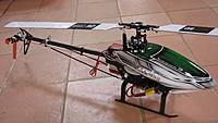
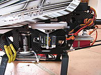
Here is my new bird. The frame is a Flybarless HK450 pro TT v2 (Hobbyking) with a few upgrades from Tarot or Align.
Detailed setup:
- Cyclic servos: 3dPro DS415MG (from rc711)
- Tail servo: TGY 316MG (Hobbyking)
- Gyro: TGZ 380. I bought it on eBay for 60$ shipped (August 2013), but it seems that it can now be found for less than 40$ . So far, in the setup/menus, I could not see any difference with the beastX v3.
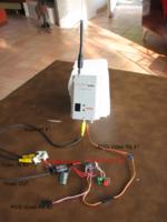
Here is the thread dedicated to this gyro.
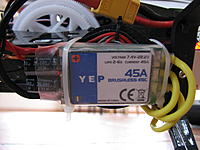
- ESC: YEP 45A (Hobbyking).
- Receiver: FrSky D4R-II in PPM mode (with telemetry monitoring the BEC voltage, the 3S Lipo voltage, and RSSI)
- Motor: 3400kv, unknown model (I bought it second hand). I would be interested to know the model or brand of this motor, so if someone recognizes it, please tell me ! EDIT: it is an NTM 3400KV 3s heli motor sold by Hobbyking (thanks ridge_racer).

I did only one short flight so far, just hovering, but everything looks ok ;-)
Posted by grmis | Jul 13, 2013 @ 03:09 AM | 33,919 Views
Here is a simple & very cheap DIY RSSI video diversity. It is based on an Arduino Pro mini (less than 4$ on eBay) and the following video switch from Hobbyking:

https://www.hobbyking.com/hobbyking/s..._Switcher.html (less than 6$)

One advantage of using this video switch is that almost no external component is needed. The video switcher is supposed to be connected to an RC receiver, but here the PWM signal needed to select the video source is generated by the arduino. I just added one push button to select one particular receiver, or the automatic mode (the one with best RSSI), as well as a 2 leds to indicate which receiver is actually selected, and what is the RSSI level (bar with 5 leds). This can obviously be extended to 3 receivers instead of 2. The system is powered by 5v taken from (inside) one of the receiver (here the 12-channel VRX sold by HK, 0.9-1.2GHz). I am using one ground plane antenna on receiver #1, and a patch antenna on the other (both from IBcrazy's design). I confess that I have not yet used this in the field... but on the bench everything looks ok

If needed (?) I could post the detailed schematics & arduino code.

Warning: some labels on the video switcher are incorrect ! Remove the cover to see the correct pin labels on the PCB.

EDIT (July 26th): I have done a few test flights with this diversity system and it works . I however noticed that some care is need to calibrate the two RSSI levels, even though the two video receivers are (in principle) identical. Their RSSI levels seem to differ a little bit and this must be take into account in the arduino code. I may add a potentiometer to be able to adjust "manually" some bias in favor of one receiver/antenna or another (at present I have to change the calibration parameters in the code -- which is not very convenient if you are on the field).
Posted by grmis | Jul 08, 2013 @ 04:05 AM | 16,306 Views
Hi,
Here is a video of my first attempt to fly with someone else doing FPV :
FPV duo: Dynam Hawk Sky following a Swift wing (3 min 0 sec)


Detailed setup. There are a few new things (highlighted in red) compared to my previous video:

- Plane: Dynam Hawk Sky / 2400kv motor [Hoffmann magnetics] & 6x3 prop / Turnigy Plush 40A ESC / 2200mAh 3S turnigy nano-tech.
- Flight controller: CRIUS AIOP v1 (HK clone in fact) + ArduplaneNG r303 + minimOSD (extra 2.2)+ uBlox Neo6 + Airpseed sensor (used for autonomous nav. modes, such as loiter or RTH).
- Video TX : 900MHz / 200mW. Antennas: DIY inverted-V & ground-plane (video link is ok up to ~1 km at least)
- Camera: Sony 600TVL CMQ1993X (from sc2000, with IR filter), 2.5mm lens.
- RC RX: 2.4Ghz FrSky D4R-II in PPM mode, PWM RSSI connected to the CRIUS board through LC filter (& displayed in the OSD). Although I think I have calibrated it correctly, you can see that the RSSI indication sometimes still shows " 99% " at a few hundred meters
- Recording (on ground): SD DVR from Hobbyking. Initially I was very disappointed by the video quality of this DVR, due to huge & numerous artifacts. Then I realized that it was a codec/viewer problem: I switched from VLC under linux to media play under windows, and now the quality is much better
- Remark: During this flight I learned that in FBW-B mode with ArduplaneNG, the elevator is inverted (thanks mkuvy).

Same flight seen from the other plane (Swift wing) :
Premier DUO FPV (2 min 9 sec)

Posted by grmis | May 17, 2013 @ 03:41 PM | 22,200 Views
Hi. Here is a video of one of my first test flights with video + CRIUS AIOP flight controller with ArduplaneNG software :
RTL with Crius AIOP+ArduplaneNG+minimOSD on Dynam Hawk Sky RC plane (5 min 14 sec)


- Flight controller: Crius AIOP v1 (Hobbyking clone)
- GPS: uBlox NEO-6M
- Firmware: ArduplaneNG (r300).
- Airspeed sensor MPXV7002DP + pitot tube from jDrones (airspeed shown on OSD but not (yet) used for navigation)
- OSD: minimOSD (extra 2.2).
- Plane: Dynam Hawk Sky / 2400kv motor & 6x3 prop / Turnigy Plush 40A ESC
- Video TX : 900MHz / 200mW
- Antennas: DIY inverted-V & ground-plane antennas
- Camera: 420TVL board camera (cheap...). 2.5mm lens
- RC RX: 2.4Ghz FrSky D4R-II in PPM mode
- Video recording (on ground): Easycap USB + Netbook + VirtualDub
Posted by grmis | May 01, 2013 @ 09:41 AM | 39,784 Views
As many people, I fried two minimOSD [switching regulator version] ... This is the faulty setup:

- 3S lipo connected to an ESC with BEC. The 5v output powers my flight controller (CRIUS AIOP) and the digital side of the minim OSD.
- The video power of the minim OSD was connected directly to the 3S Lipo (~12v).
- This worked for some time, but then, the MAX7456 chip died during tests (Atmet chip still ok, but no video output).
- The cause is still not completely clear to me... However, the Maxim data sheet says that there should be not more than 0.3v difference between the digital and analog grounds. Since I used a single battery, the two grounds are connected (via the lipo, the ESC and the CRIUS board) but when you plug/unplug it could be that there is a transient voltage difference exceeding 0.3v ?

- Anyway, you can ask for some free 'sample' MAX7456 chip on Maxim's web site (for test/evaluation purposes) to repair a fried OSD .
This is how I did it:

0) Check that the Atmel chip is ok by connecting your (dead) minimOSD board to the configuration software.
1) Remove the Max7456 chip, cutting the leads with some hobby knife (no special soldering tool needed).
2) With a small iron tip, remove the small pieces of leads left on the board. Check that you did not shortcut two neighboring pads.
3) Solder the new chip - a magnifying glass helps. This is the slightly delicate step if you are not too familiar with soldering. I did it without flux, but it is probably better to use...Continue Reading
Posted by grmis | Apr 17, 2013 @ 04:10 PM | 36,048 Views
Hi,
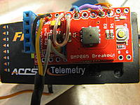
Let me share this cheap and simple barometric altimeter. It is largely based on this altimeter (by KapteinKuk), except that it uses a cheaper BMP085 sensor, and the altitude is sent to the ground via an FrSky telemetry link. It also sends the time from start, the current temperature and the max. temperature. All these data appear on a FLD-02 telemetry screen for instance. A lot of informations concerning the FrSky serial telemetry protocol (including links to several arduino codes) can be found on this thread.
And here is another similar project: OpenXVario.


To get a reasonable accuracy, the arduino code makes the average of 10 consecutive measurements and sends the results every 300ms. The accuracy seems to be of the order of 1~2m. This can be made more accurate by taking more, say 30, measurements and sending the result once every second (conversion time is about 30ms).

Here is the code:
Code:
#include <LiquidCrystal.h>

// Author: Grmis, 04/2013
// Arduino Pro Mini 3.3v connected to BMP085 barometer breackout
// throught I2C
// Arduino connected to 'RX' line of FrSky D8R-2 receiver
// through digital Pin (use SoftSerial with inversion)
// Although the arduino is 3.3v, it seems that the 5v receiver understands it :-)

// code based on the original codes by:
// Rolf R Bakke
// R.Schlohan
// BMP085 Extended Example Code by: Jim Lindblom (SparkFun Electronics)


#include <Wire.h> // I2C to communiucate with the sensor
#
...Continue Reading
Posted by grmis | Mar 25, 2013 @ 06:25 PM | 19,318 Views
Two days ago I did the maiden flight of my autopilot system:

- Plane: Dynam Hawk Sky
- Flight controller: CRIUS AIO Pro (v1, first batch sold by HobbyKing)
- Software: ArduPlaneNG (r268). I found a lot of useful informations on the blog of Jean-Louis Naudin.

- For the PID parameters, I took those given here for the bixler. However, because the plane is somewhat overpowered, I reduced to 50% the max throttle in auto mode, and set to 35% the cruising throttle.
- GPS: uBlox LEA6H
- Receiver: FrSky D4R-II in CPPM (PPM SUM) mode (single wire going to the CRIUS board). One just has to add ' #define SERIAL_PPM ENABLE ' in APM_Config.h, and the PPM_SUM line goes to the throttle input of the Crius board.

I tested the stabilize, fly-by-wire-A (FBWA), return to launch (RTL) and Loiter modes with success . With some wind blowing at 10-20km/h the loiter trajectory was not quite a circle, but ok. Otherwise the plane was stable and ArduplaneNG nicely managed the throttle to maintain the speed and altitude.
I am now waiting for a minimOSD to install the FPV gear back in the plane.
Posted by grmis | Mar 21, 2013 @ 12:40 PM | 17,210 Views
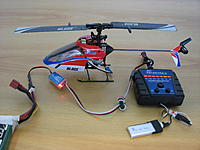
For completeness, I am adding my last (but not least) bird to this blog. No much to say, everything is stock, but it is a great little machine !

Just notice on the picture that one can use a (switching) UBEC to power the Celectra charger with 6 volts. This way I can charge the mCPx lipo from a larger Lipo, no need to have a wall plug.