Archive for May, 2018
-
 Views: 63
Balance plug extension before the gentle tug test. -
 Views: 73
Gentle tug on the red wire easily pulls out of the white housing. -
 Views: 71
The top of he white plastic housing is cut away to show how he crimp connectors are secured. On the bottom of the metal crimp is a small barb that catches into a plastic hole/slot .
Comments (0)
Add Comment
-
 Views: 66
Landing in rough terrain outside the fenced in landing area caused the floats to break away from the plastic mounting pads. Still had power to flight controls but no motor thrust. -
 Views: 69
No damage to prop or airframe other than the two floats. -
 Views: 83
Note the plastic mounting pads are not attached to the foam floats. Gorilla Glue over night re secured them. Nose cracking was repaired with CA and kicker. The internal float servo worked intermittently and was replaced. -
 Views: 70
The Turnigy 40 A RClander is on top. The new AeroStar 60 A RVS model is on the bottom. It’s instructions are included in the pack. Purchased from Hobby King.
-
 Views: 71
Custom Voice Events shows what is on each switch. Missing is the aileron to rudder mix audio. -
 Views: 77
Nothing unusual here -
 Views: 74
-
 Views: 84
Main screen shows both elevator and motor on low trim. Crosstrim used for elevator. -
 Views: 81
The Channel 5 Gear switch is on E and reverses the ESC/motor direction. The SAFE Self Level On/Off is on Channel 7 Aux2 B switch. -
 Views: 64
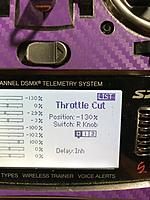
The Throttle Cut on the right knob is not for everyone. But if you have the knob and don’t use it then I think it’s a good idea to put the throttle cut on it. Half the knob is painted red (motor on) and half is white (throttle cut).
-
 Views: 82
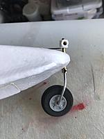
Left and right nosewheel struts are bent aft for castoring. The left one shown has the stock rudder steering arm that connects to a wire pushrod to the stock rudder servo. -
 Views: 79
CA used to bond the plywood to the foam -
 Views: 68
Aft main wheels stay fixed. The compartment is sealed with Gorilla Glue and painted with Testors white enamel. -
 Views: 79
After the nose is sliced a template is made for the 1/8 inch thick steering tube support. Cloth or glass is CA’d to the tube and wood for added strength. -
 Views: 62
Two Visegrips are used to bend the wire. -
 Views: 66
Hobbico HobbyLite filler is used to fill the slot. White paint, clear epoxy, or Polycrilic can be used to seal this area. -
 Views: 54
The right nosewheel is a castoring type and works to support the left steering nosewheel. -
 Views: 73
Top view of slot. A piece of 1/16 ply wrapped with 100 grit paper opens the slot for the 1/8 inch thick ply steering tube support.
-
 Views: 82
Foam cut out reveals hollow insides. -
 Views: 80
Box cutter used to slice foam. -
 Views: 74
Blade should be perpendicular for wheel box to fit right. White Gorrila Glue will fill cracks and voids. -
 Views: 87
1/8 inch Lite Ply was used to construct the wheel box. The axle and wheel collars are positioning the wheel in place. Epoxy allows time to adjust the parts so the wheel is parallel to the sides and perpendicular. These tires are of unknown origin.


