Jack Crossfire's blog View Details
Archive for May, 2016
Posted by Jack Crossfire | May 29, 2016 @ 10:33 PM | 9,725 Views
In the scheme of things, microcontrollers are brought up in 4 steps:

bootloader
peripherals
communication
user program

Another 2 weeks got all the Feiyu peripherals working. It uses the SPI, I2C, PWM, ADC, a quite massive number of peripherals. The mane issue was the I2C driver. It doesn't work if a UART sharing the same pins was enabled at any time in its past. The UART has to remane disabled from startup. So a new bootloader which didn't enable UART3 went in the board which uses I2C. Ideally, all 3 bootloaders would only enable UART3 if the user sent it a passthrough command, but for now, 1 bootloader is hard coded with it off.

Couldn't get I2C to the 1Mhz probed. It only went to 100khz, which was fast enough for over 400 IMU readouts/sec, but not as low as Mr. Feiyu himself in latency.

The mane clock had to be reset in the user program, after the bootloader already set it. The C library start functions reset it back to 8Mhz.

SPI had a strange bug where the SPI_FLAG_BSY bit had to be tested instead of the SPI_FLAG_RXNE bit. The SPI_FLAG_RXNE bit cleared long before it was done transmitting. Also, the user has to read DR after every transaction or it won't fire again.

The hall effect sensor produced valid data, despite the lack of any datasheet.

The mane trick in enabling the motor was creating deadband between the N & P pulses. That required setting the TIM_BDTR_OSSI in the BDTR register & setting the DTG bits to the deadband time. There are...Continue Reading
Posted by Jack Crossfire | May 28, 2016 @ 09:36 PM | 9,526 Views
Deuce Bigelow isn't known for before & after photos, because his modules aren't really as inflatable as balloons. The 1st 2 were privately funded cylinders launched on Proton rockets, back when Proton rockets worked. They didn't expand in length & only slightly in diameter.

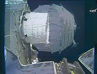
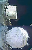
10 years & a few waves of RIFs later, they finally launched their last module using NASA funding. 2 months later, it was inflated. There are no official before & after photos, but some careful editing revealed the size change. It was a bit more impressive in length than the 1st 2, but still not inflating significantly in diameter. It has no life support, relying entirely on the space station for air. It can't be used for living space.

Their plan is in 5 or 10 years, with any luck, getting a 43,000lb module up. Too heavy for a Falcon 9, so it would require an Atlas 5. There are no diagrams of how an inflatable module is built, but it is known that the walls contain bladders which dictate the shape of the module. The bladders are filled to a different pressure than the habitable space. The walls of the NASA module were not disclosed. The walls of the hypothetical 43,000lb module would be 18in thick.

For all the efficiency of spherical space stations, the modules can't be spheres. They have to be confined to the shape of the payload fairing, which is still a cylinder.

For all the complexity of inflation, inflatable modules don't increase the amount of junk you can put in...Continue Reading
Posted by Jack Crossfire | May 28, 2016 @ 12:17 AM | 9,436 Views
Not easy to think about anything else, after the video. You know the one. We all grew up watching the Apollo 4 stage separations & the Apollo 6 earth departure stage departing while the camera stayed behind in the S-II stage, & the shuttle departing the boosters. Nothing was quite like watching a 1st stage manipulating grid fins & engine burns to return from a parabolic arc to a powered landing on a tiny X in the sea.
Posted by Jack Crossfire | May 22, 2016 @ 09:14 PM | 9,655 Views
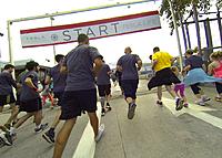
The answer is no. Elon Musk wasn't at the Tesla factory 5k.

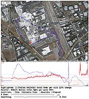
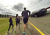
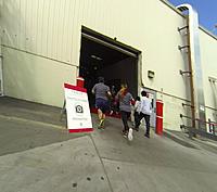
Started getting nauseous near the end, but overcame it by throttling back. Real hot in the factory. 1 mile of it was in the factory, winding up & down what seemed to be the entire assembly line, though the fake test pilot couldn't differentiate different car models or different states of completion. They all looked nearly finished. The robots were quite enormous & organized into discrete work cells, separate from areas with manual assembly. They had stopped production, but some people were walking around with parts, not happy to be working on Sunday.

A lot of people walked the course, making a factory tour out of it. The fake test pilot sped through, as usual. Just can't slow down in a 5k. The magic would have been if the robots were left on, revealing production techniques. Surprised fake test pilots could sustain such a high speed for so long. Threw down an average speed of 7m29s/mile.
Posted by Jack Crossfire | May 21, 2016 @ 01:44 AM | 10,727 Views
ARRESTED FOR RIDING A BOOSTED BOARD? (9 min 17 sec)


It wasn't that Neistat was busted for riding his Boosted board on a bike path. It was that he was busted 1 week after the fake test pilot was busted for driving the lunchbox on a bike path. Government budgets must have finally grown enough to enforce those things.

It was a routine 18 miler just after dark. It was completely empty. The vehicle & human had sustained 9min/mile quite easily for 3 miles. Saw 2 cop cars parked next to Walmart. Saw some years ago, so it seemed to be a common beat to park next to Walmart & eat the donuts. The cars were empty. Passed a homeless guy who was standing in the middle of the trail, seemingly confused. In the distance were 2 guys, probably dog walkers.

The 2 guys shined flashlights at the fake test pilot, not uncommon. What was uncommon was the lights followed me as I got closer. Saw they were cops. Then they said "Hey! Can we talk?" It was the 1st traffic stop of a runner for using a robotic pacer, probably in human history.

The elevated heart rate & breathing from running 3 miles made for an intense dialogue. "What is this machine doing! You know motor vehicles aren't allowed! Neighbors & bikers complained about RC cars! There's a $250 fine. We're not going to fine you now, but someone else may not give you the same courtesy!"

As the fake test pilot cooled down, they got more peaceful & asked how fast it went, if I...Continue Reading
Posted by Jack Crossfire | May 17, 2016 @ 11:27 PM | 9,582 Views
Basically, a loudspeaker for the exercise robots would be nice, but dynamic speakers are too heavy to cost effectively move. Thus, a practical use for electrostatic speakers appeared. Electrostatic speakers are used in a Best Buy demo for a game. Typical for the age, there's very little online information on how to make an electrostatic speaker. There are no specific voltages or currents. The only fact is the driver part of an electrostatic speaker is much lighter than a dynamic speaker.

The only useful parts list is on:

http://jazzman-esl-page.blogspot.com/

There are no useful schematics, but notes on the speaker performance here:

http://sound.westhost.com/project1053.htm

The Elliott speaker uses the audio amplifier to power all 3 plates. The Jazzman speaker uses a separate supply for the diaphragm. They all passively power the stators by stepping up the audio amplifier voltage.

Presumably, the stators go at 1000V. The diaphragm goes at 2500V. The required power is unknown, though they say the speaker presents a 4uF load which requires a lot of power, maybe even more power than a bug zapper or cold cathode. The transformers are very large, but what if the audio amplifier could be actively stepped up by a semiconductor solution. It's unlikely a semiconductor solution would generate enough power, but it might work for a very small speaker.

Barring the electrostatic speaker, there's using some combination of piezo buzzers to obtain lower frequencies. Perhaps 2 piezo buzzers on opposite ends of a large resonator could alternate single pulses.

10 years ago, there was an effort to make a speaker which used any plastic surface as its resonator. It was targeted at eliminating speaker grilles in gadgets by using the enclosure itself. It went absolutely nowhere.
Posted by Jack Crossfire | May 15, 2016 @ 07:49 PM | 9,867 Views
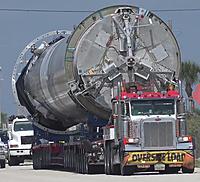
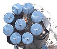
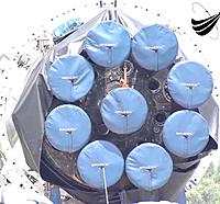
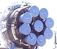
Recovered Falcon 9 fotos are hard to come by, due to the secrecy of a commercial operation & the lack of interest compared to more important matters like Trump's imminent non election.

US Launch Report is the only guy covering recovered booster processing.

https://www.youtube.com/channel/UC5h...eKgYmVryCEyJYA

Like the shuttle booster recovery, every flight is still a major construction project. Still kind of novel seeing ordinary construction cranes of the past 30 years handling the alien looking landing legs, like humans with limited means trying to figure out how to move parts of a giant alien robot.


In the 1980's the visionaries we read about were Werner Von Braun, Thomas Edison, Nicola Tesla. The common theme was they all existed in the past. There weren't any visionaries in the present because the odds were too remote for our generation to coincide with someone like that. Musk is the closest to being a living Werner Von Braun, but Werner Von Braun actually saw his giant moon rocket come to fruition, even if his Mars vision never happened.

There isn't much to the Musk story which hasn't been done before. Kerosine rockets & labor intensive recovery of damaged boosters have been done before. The talk of a mass produced electric car, gigafactory & self driving cars is still talk. He hasn't realized the vision of airline style rocket reuse or travel to Mars. His car & solar companies are financial disasters.

At least there's...Continue Reading
Posted by Jack Crossfire | May 14, 2016 @ 08:54 PM | 10,044 Views
After many traps for young players, the Feiyu began running a custom bootloader. Key points were converting the GPIOs from JTAG, changing a bunch of HAL code . Once complete, there will be no need for the Nordic board or all the wires. The trick is going to be daisychaining all 3 boards & fitting everything in flash. It may seem pointless to reconstitute such a low end chip, but it is what made the Feiyu the small size it is. The mane problem is all this is for just 1 copy of 1 product that was only made for 3 months.
Posted by Jack Crossfire | May 08, 2016 @ 04:23 PM | 10,444 Views
So the mane processor is an STM32F103C8 64K flash, 20K RAM, 72 Mhz, 48 pins. It breaks out single wire debug on pins 34, 37 for raw programming. It also breaks out 3.3V, GND to the programming header.

There's no distinguishing feature for the chips to detect which board they're on. It must be programmed in the bootloader or some initialization handshake.

MOSFETS are connected directly to GND & battery V+. They're some kind of motor controller packages with complementary MOSFETS.

switching regulator reduces battery to 5V
linear regulator reduces 5V to 3.3V
STM32 VDD comes from linear regulator
LMV358 VDD comes from linear regulator
hall effect VDD comes from linear regulator

Header entering yaw board:

RX/yaw PWM -> 100R to pin 43/UART1_RX/I2C1_SDA/TIM4_CH1
TX/pitch PWM -> 100R to pin 42/UART1_TX/I2C1_SCL/TIM4_CH2
GND
8.4V
Mode PWM -> directly to pin 41/TIM3_CH2
video

Header exiting yaw board:

100R to pin 21/UART3_TX/I2C2_SCL/TIM2_CH3
100R to pin 22/UART3_RX/I2C2_SDA/TIM2_CH4
GND
8.4V
unused
video

Board to board wires are straight through. The boards communicate via UART at 2Mhz. Colors are reversed on the IMU wire but I2C connects to the MPU-6050 as expected. I2C goes at 1Mhz.

Hall effect sensor uses SPI. Clock speed is 561khz. Chip select goes low 1st. The STM32 sends a command in 16 bits, switches the SPI to input & reads the result in 16 bits. Chip select goes high last. Sequence repeats every 300us. Doesn't have an initialization...Continue Reading