Posted by Jack Crossfire |
Feb 27, 2009 @ 01:25 PM | 6,406 Views
The answer is no. U couldn't survive audible sonar pings 4 more than a few minutes, not even the mighty Ubuubu.
Now what if there was an audible sonar ping you humans could stand. Adding small amounts of noise to the waveform definitely improves it. Receiving musical pings would require huge amounts of electronics.
Noisy 3khz could be close to a jet engine if U concentrate. At 3khz, accuracy drops to 4" but it's a frequency U could filter purely in software, given a 3 channel sound card & perfect realtime capturing which doesn't exist.
U only need 6khz to capture 3khz. 18khz to capture 3 channels of 3khz. 1 output pin to control AGC by PWM. It could probably handle musical pings. If only information traveled slower through air.
There R only 2 speeds information can travel through air:
740mph
300,000,000m/s
That's it. No matter how hard U try, U can't go at any other speed. 100mph would be good for sonar. 1mph would be good for taxes. 600,000,000m/s would be good for paychecks. It's not going to happen. Taxes always go 300,000,000m/s & paychecks always go 740mph.
No matter how much U worship & sacrifice to the god Ububuu, he can never wake up & say, "For renewable sonar, I command the congress to make soundwaves go 100mph. Paid for by just the top 0.00001% of earners! Yay!" even though most of U think he can.
Posted by Jack Crossfire |
Feb 26, 2009 @ 02:42 PM | 6,760 Views
Did indeed capture some Maxbotix output using ADC's at 1800Hz & the pings showed up nicely. U could use that for an AGC which defeated reflections, but we're done with sonar. Unfortunately the screenshots R lost, just like the memories of 7.25% sales tax, $1 gas, & $7.50 movies.
Also, before we give up sonar, the optimum frequency for the Maxbotix's was somewhere around 55khz, not the 40khz advertised. The transducers probably need manual tweeking, another reason 3D sonar would have problems.
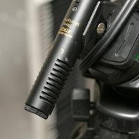
Finally, tried capturing 10Hz sound with our best condensor microphone. Remember back when U actually bothered with decent microphones & watched home movies on giant screens instead of tiny Goo Tube windows?
Forget about 10Hz sonar. It would take kilowatts of power & ginormous transducers. With a few hundred watts & 30lbs of wood, U can get the condensor to pick up 30Hz.
There are delusions of audible sonar. It would drive people away from the blades. It would be omnidirectional & low powered. The main problem is interference, so what if instead of a sine wave, U spanned several frequencies. The output would be a fixed pink noise pattern U can sense the phase of & a real expensive filter to capture it.
Posted by Jack Crossfire |
Feb 25, 2009 @ 02:36 PM | 6,718 Views
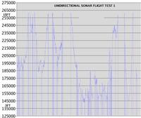
Finally got a 1 way sonar test in the air. It was pretty horrible.
Forget about 1 way sonar for large copters, camera stabilization, or any of that other stuff. It's too directional. U would need dozens of the Maxbotix's to cover the full area. It would cost more to make Maxbotix transducers work than to buy an RTK GPS system.
For a large copter, it only works if you're directly over the sensor. No problems with reflections outside. U can go to 15ft before the signal dies. Below 3ft U could fly sideways for some distance. The only explanation is signals bouncing off the ground & off the propellers.
For an indoor micro copter, there's a chance U could fly it in a small box over the transducers.
Your only hope is to find a truly omnidirectional & super powerful transducer other than the Maxbotix. Good luck with that. Don't U know the world is based on mortgages & cars?
Serial port multiplexing was a failure. The XBee packet timing is not predictable enough to stuff data between packets. RTS doesn't work either. It splits packets. Time to go back to 50Hz with dual serial ports.
Anyone serious about commercializing VicaCopter would use bluetooth or a direct USB connection & skip the serial ports.
What about reflected sonar for position sensing? U ask. You'd have to always fly 1 meter away from & perpendicular to 2 walls. It's a $75 tag just for 1 down & 2 sideways sonars. You'd single handedly bail out Minnesota's mortgages.
What about 10Hz sonar? 10Hz would be omnidirectional but requires a very heavy magnet.
Posted by Jack Crossfire |
Feb 24, 2009 @ 02:37 PM | 6,696 Views
Another amplifier stage & the dual sonar receivers started working. Anything can be fixed with more op-amps. This circuit is now over 1000000 gain. The receivers worked with all our op-amps, but old problems returned.
12" sensor spacing was pretty good at sensing 2 dimensions in a 4' line 5' above the sensors. Most of the time it got within 1". Distance readings R pretty stable throughout the week, as we increase the sensor count.
Forget about any lower. There's no way a full sized airframe is going to hold its position accurately enough for this to work. We're down to finishing ghetto rotor & flying to higher altitudes with the sonar to get full ranges with engine noise & without reflections.
With all its problems, patents, & high prices, custom sonar is very depressing. Who knows what would happen if the sonar banging was combined with the eternal blizzards of Minnesota.
Posted by Jack Crossfire |
Feb 23, 2009 @ 02:26 PM | 6,372 Views
Maxbotix gives no rights for the reference design so you couldn't use it in a product unless you moved to China.
Building your own sonar transmitter, writing your own firmware, & removing all the shrouds produces the best results so far. We have 1/4" precision in the best circumstances & a much wider cone.
The range is still very limited before reflections overwhelm the original signal. Eventually the AGC adapts to the reflections instead of the incident signal.
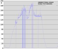
If the sonar modules point straight at each other, you can get 10ft indoors before they start falling over. Looks like ghetto copter is going to fly in a straight line from the ground station & have a fixed heading.
Being experts in 1 dimensional sonar, you're now ready for 2 dimensional sonar. After fabricating module #2, no op-amp would work besides the 1 we tested all week. Back to the commute.
Posted by Jack Crossfire |
Feb 21, 2009 @ 09:58 PM | 7,460 Views
With all the timer issues found, the results are pretty dissapointing. Accuracy is 1", deteriorating as distance increases.
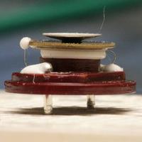
Removing the shroud doesn't make any difference for the receiver but greatly reduces the transmitter power. Suspect it's supposed to amplify the sound by resonating.
The useful range is only in a small cone.
You can improve the range by angling the transmitter & always aiming the aircraft at the receivers but this costs you altitude readings.
Keeping the ground station far away from the amplifier improves results.
The automatic gain control works. It gets as much information out of the transducer as you can get.
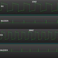
The update rate is 15Hz because the Maxbotix firmware can't go any higher.
The Maxbotix firmware is so limited & expensive, probably going to forget about reflected altitude readings & shoot for 3 receivers & 1 transmitter.
Posted by Jack Crossfire |
Feb 20, 2009 @ 01:44 PM | 6,303 Views
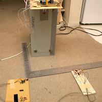
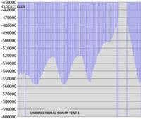
After another 2 hours in the traffic jams, got all the way to the first unidirectional sonar ranging. Only got it to work by pointing the modules straight at each other. The maximum range was only 5ft. We have broken synchronization, broken XBee multiplexing, broken clock synchronization, broken gain. The number of systems which have to be upgraded for this to work is nihilistic. It definitely has 50 more hours of commuting to go.
XBees are a complete waste of time for an indoor micro copter. Multiplexing XBees with 72Mhz is freakishly wasteful, maybe even more than raising taxes to fund prime Bakersfield mortgages. We only do it to reuse the same equipment with the full sized copters. You'd ideally use bluetooth.
Posted by Jack Crossfire |
Feb 19, 2009 @ 03:17 AM | 8,605 Views
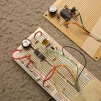
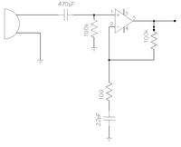
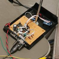
There it is. The Jack Crossfire version of the Maxbotix amplifier. No matter how much money your boss makes by copying reference designs, we hate copying reference designs. So after several hours of trying components, made a slightly simpler version of the Maxbotix amplifier. It isn't as stable as the Maxbotix, but it has longer range & you can fix the output in software.
Using Fry's ripoff parts, this circuit + the transducer cost 1/2 as much as buying a full Maxbotix for reception. If you want the full measuring device, you're better off paying full price.
This circuit is extremely powerful. Indoors, it senses the transmitter from 10ft away, mostly omnidirectionally. It can sense the transmitter 20ft away if they're pointed at each other or there is a reflection. The trick with indoor operation is reflections from indoor objects. It won't do as well outdoors. It's sensitive to ambient noise, clapping, & probably aircraft.
Since we caved in & threw in tons of op-amps, we might as well run the transmitter off a 20V op-amp & see how far that reaches. You can also try putting a diffuser under the transmitter. That would require losing altitude sensing by reflection & building 3 of those reference designs, so forget about it until the system actually flies on 5V.
Posted by Jack Crossfire |
Feb 18, 2009 @ 01:34 PM | 8,269 Views
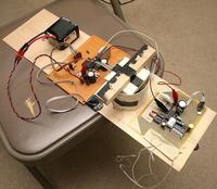
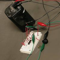
So after 7 days, the unidirectional sonar test kit finally made it out of the wasteland. Put a simple 1000:1 high pass amplifier on it. Sadly, it's very directional. The more you amplify it in hardware, the more directional it is. In software, you can do all kinds of things to it, but we don't have the luxury of a 40Mhz sound card.
Running it on 5V definitely improves the range. Unfortunately you're stuck with a very small cone of visibility in front & above the transducer. The range is stuck under 5ft. You'd have to use takeoff tricks again, just like with GPS. Running it over 5V would require a matched impedance power amplifier. You can't just plug it into a BJT.
With the constant rain & all you job seekers pouring in from the wasteland, we're spending hours & hours on the freeway. Only got a couple tests in with the Maxbotix's.
Future options:
Build the reference design.
Grind up the Maxbotix's to try to make them more omnidirectional & forget about using bounce mode for altitude.
You can keep spending money on this until you're up to
http://www.evolution.com/products/northstar/works.masn this $1300 positioning system. The web pages have no information & he's got no advertising, but it's machine vision.
Posted by Jack Crossfire |
Feb 17, 2009 @ 01:55 PM | 7,729 Views
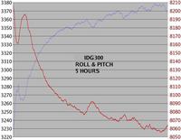
You can get the worst case drift from the datasheet. They all have a null drift over temperature or zero rate vs temperature parameter. If it's in volts, you divide the volts by the volts per deg/sec parameter. This is the key parameter 4 U.
IDG300: 150 deg/sec
IDG500: 25 deg/sec
ADXRS150: 26 deg/sec
MLX90609 - 150: 7.5 deg/sec
LISY300AL: 5 deg/sec
So we got the 2 worst gyros in the world. 2007 was the dividing line where they got a lot more accurate, except for the Silicon Valley ones. No-one is anxious to spend $100 on LISY300AL prototyping boards, so the idea of accurately predicting the outcome of cheap gyros without buying a PC board is dead.
The days of magnetometers & accelerometers are over. If they're really down to 5 deg/sec, modern IMU's can go for over 20 minutes without any corrections.
FYI, polulu.com has the same breakout boards as $parkfun for slightly less money. The polulu LISY300AL can take 5V & lowpass filters the output. You need a 3.3V reference either way because A/D converters are nonlinear.
Posted by Jack Crossfire |
Feb 16, 2009 @ 08:25 PM | 6,980 Views
Still having delusions that 2 years of experience could somehow salvage some use from the IDG300's, put them back in an IMU. Also, if U can get the IDG300's to work, you guarantee any other gyro will work.
They're still pretty awful. The body heat from sitting next to them or the radiated heat of a heatsink throws them off, but they are stable at constant temperature. They would make good thermometers. Can't believe $parkfun still sells them for $75. No Silicon Valley startup is ever going to make good gyros because all the aerospace engineers are in LA.
Thermisters suck. Thermisters require 2 more analog channels. They can't measure temperature inside the gyro package. Without a proven cheap gyro solution, the sonar doesn't have much of a future either.
Posted by Jack Crossfire |
Feb 15, 2009 @ 06:12 PM | 7,063 Views
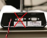
Since the ground station is getting major rework to support sonar, decided to get rid of a serial port.
The answer is yes. You can multiplex a 2.4Ghz & 72Mhz on the same serial port. The trick is to use lots of diodes & carefully time the incomming 72Mhz packets to fall where the incomming 2.4Ghz is normally idle. The outgoing packets are received by everyone. The maximum feedback rate drops to 40Hz & the 2.4Ghz bandwidth drops to 20kbits. The 2.4Ghz has an RTS pin to make it stop sending, but you can't split the 2.4Ghz packets so RTS is useless.
The dual serial port ground station could have been used for anything, but money & complexity is more important. Now it's only for controlling copters, but it's much simpler to set up & cheaper.
Posted by Jack Crossfire |
Feb 14, 2009 @ 10:11 PM | 8,654 Views
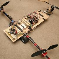
The reflected sonar works about as badly on the tri rotor at 3.3V as it did on the T-Rex at 5V. It can probably be used below 6ft in reflected mode with a lot of massaging. Unfortunately, you'll have to focus on unidirectional sonar for the full sized airframes.
The answer is no. There's no way 2 crystal oscillators are going to stay synchronized enough for unidirectional sonar to work. Clocks R accurate enough for digital audio players to sound synchronized, but not enough for sonar. U need a way to synchronise the clocks.
The way U do it is by broadcasting simultaneous radio beacons to all the microprocessors. Each microprocessor sends back its clock value when it got the beacon. Since the radio beacons all have mostly the same latency, the broadcaster can then compute the drift. U don't need to calibrate the sonar anymore with this either.
Since the drift is linear & constant, U can use least squares to get really accurate values, but we're sticking with averaging to get sonar tested as fast as possible & keep U entertained. The XBees can get the drift between each microprocessor to within 10 microseconds or 1/4" of sonar. The actual sonar transducers R going to be much more unstable.
Posted by Jack Crossfire |
Feb 14, 2009 @ 12:39 AM | 7,675 Views
Don't be surprised if the camera stays earth bound until the sonar obsession wears off. We're going to use DT700's, 30A ESC's & large corotating props for the camera. To make the Chinese shipping economical, this has to be combined with the orders for ghetto rotor & pocket drone. Maybe we'll just move to China & be done with the hassle.
Have a budget for an extremely small servo or biometal actuator for yaw. Looks like the micro RC parts & bio materials R becoming more common & cheaper. Bio metal would drastically cut the weight of the yaw control. Most of the cost is patent royalties.
No-one has ever documented a coil servo in motion. From the low resolution pictures, they appear to have a permanent magnet outside the coil & a permanent magnet on the armature. When the coil is off, the outside magnet pulls the armature. When the coil is on, the coil pulls the armature away from the outside magnet. The armature has a source of friction to stabilize it.
We'll probably end up with a DIY linear motor. Oh & 1 other thing. If U think the pocket UAV hasn't already been done, think again. The inventor of the Picco Z already made one. It's a fully autonomous, gyro stabilized Picco Z being sold to European governments to fight the red menace. The red menace across the pond, that is.
Pocket Drone
Posted by Jack Crossfire |
Feb 13, 2009 @ 01:04 AM | 6,908 Views
The camera's first autonomous takeoff, pirouette, & landing was looking good until the descent. Managed to jump in & rip out the power cable before the fire destroyed all 2000 of our last paychecks. The crash movie was lost when the camera powered off, but with the magic of mplayer we got it back. Take a look & listen to the sound of motor death followed by fire. The 18A ESC's were overloaded by the weight of the camera.
So much for any spare parts for ghetto rotor. The ESC's overloaded because the payload was unbalanced & we had no tactile feedback with the autopilot. Installed the battery in the forward slot instead of the aft slot where it's supposed to go for payloads.
Nevertheless, the 12x3.8's probably can't generate any more power than the 10x4.5's because that's when the ESC's burn up. Need lighter electronics.
Posted by Jack Crossfire |
Feb 12, 2009 @ 03:47 AM | 6,680 Views
$parkfun took 2 days to process the more sonar transducer order. Meanwhile, tied a 1000:1 amplifier to the EZ-1 transducer & recorded the pulses. Take a look. Unfortunately, this oscilloscope removes DC offset & only samples 96khz so the waveform is pretty worthless. It's just enough to show sonar would probably work with just a simple amplifier instead of a horrific analog circuit.
So if U want the most bulletproof communication, U need adaptive frequency hopping. 2.4Ghz Xbees don't do adaptive frequency hopping. U would need to use API mode to change frequencies fast enough. The algorithm would work like this:
Constantly hop between all frequencies to map out what frequencies R good.
The ground station maps out the best frequencies by counting errors & weighs packets towards those frequencies.
The copter starts by listening to 1 frequency & the ground station starts by hopping the current pattern.
Every packet from the ground station contains the current hopping pattern, the start time of the hopping pattern, & the current time.
The ground station changes hopping patterns at certain intervals. It broadcasts the new hopping pattern & new start time a certain time ahead of schedule so the copter can update.
To change patterns, the ground station needs to receive at least 1 packet in response to the current pattern.
In case the copter doesn't get it in time, half of the time slots are the same as the previous pattern & these slots cover all the frequencies. It takes 2 new patterns to replace the pattern completely.
Posted by Jack Crossfire |
Feb 11, 2009 @ 03:40 AM | 6,526 Views
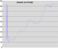
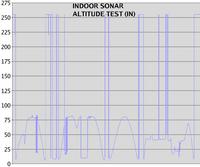
The Maxbotix is back. This time, we've cannibalized the GPS UART for sonar testing & gotten better results. It accurately measures height in the dumpy apartment, up to the ceiling, with the motors off, & using 3.3V. We'll see how it does in a flight someday.
Posted by Jack Crossfire |
Feb 10, 2009 @ 03:45 AM | 6,332 Views
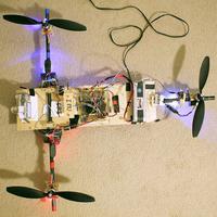
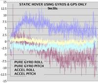
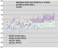
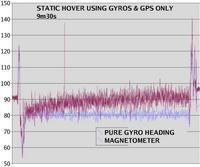
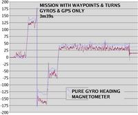
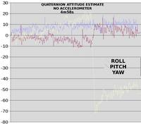
The answer is yes. The trirotor can fly itself with gyros & GPS only. Position sensing on the uBlox is good enough to compensate for the slow drift & an IMU based on ADXRS150's is a thoroughbred. This can cut $90 from an autopilot.
It is slightly sloppier than the 7 degree of freedom IMU. The quaternion becomes more unstable as the angles drift farther apart. There is a limit to how much maneuvering you can do & the flight time. But this system is immune to electromagnetic problems. Might skip the magnetometer forever.
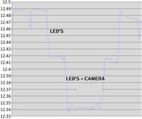
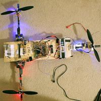
Corotating 12x3.8's generated enough power to lift the camera. The battery was pegged at the cutoff voltage for the entire 5 minute flight & the motors were smoking, but it did it. Without the camera, the 12x3.8's got the same flight time as a quad rotor. If counter rotating 12x3.8's were part of the next economic stimulus package, we'd be golden.
Posted by Jack Crossfire |
Feb 09, 2009 @ 03:00 PM | 6,449 Views
The answer is no. The tri rotor doesn't have enough power to lift the camera. Don't expect any DT750's to appear. It's always easier to lighten the payload than increase the power.
Want to combine the fabrication of a new, el cheapo system with the lightening of the payload on the tri rotor. Mainly a system that uses only gyros & sonar & takes short flights.
Would now say the 50Hz radio is more stable than 25Hz but nothing critical. It doesn't oscillate as much in orientation.
Posted by Jack Crossfire |
Feb 08, 2009 @ 09:33 PM | 5,479 Views
They have automatic throttle calibration which can't be disabled. If they go over the default maximum, they normalize all other values to the new maximum. You'll find your multi rotor vehicle starting out balanced & always pulling to one side after some stiff maneuvers.
Now a message from your sponsor.
In the 80's, almost all parents worked. There were no "stay at home moms." "Housewife" was a bad word. The term "latch key kid" wasn't invented yet.
TV stations were quick to capitalize with a block of daily animated shows from 7am to 8am & again from 2:30pm to 5pm on 2 channels. The most popular shows were on between 3pm & 5pm. You were lucky to wake up early enough & have enough time before school to reach the morning shows & you were lucky to get home in time for the 2:30 show.
There's no archive of TV schedules on the internet. Goog's future hit will be the TV schedule archive. It went something like this during the peak of the 80's:
7-8 am: KBHK: Gumby/Galaxy Rangers
2:30pm: KBHK: voltron
3:00pm: KTVU: thundercats KBHK: inspector gadget/heathcliff
3:30pm: KTVU: smurfs/Scooby Doo? KBHK: starblazers/robotech/captain harlock/Dennis the menace
4:00pm: KTVU: GI joe
4:30pm: KTVU: transformers
If 1 channel was a crummy episode or Sutro tower was down, you'd watch the other channel, so the times R a bit foggy. KBHK would always be static in lousy weather.
We learned more from afternoon cartoons than we did from Calif* public schools. We would never raise a kid in Calif*. Calif* public school kids can never reach the human potential no matter how hard they work. Indians move here to make tons of money & put their kids in public schools. The Indians only get hired because of their Indian education. In exchange, they enslave their kids to a future of begging & wondering why their XBees don't work.
 Views: 272
  Views: 258
  Views: 222
  Views: 213
