Jim.Thompson's blog View Details
Posted by Jim.Thompson | Feb 09, 2023 @ 04:05 AM | 10,679 Views
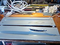
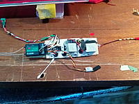
I am just putting finishing touches to my latest creation.
The wing ribs were constructed from scrap foam and hot wire cut using the "laser method".
Uni carbon main spars rolled on golf club handles of two different sizes to suit the double tapered panels.
Some stats:
S3021 airfoil section.
Wing span 2950 mm.
Tail boom wound on a pool cue.
AUW circa 1450 grams - not balanced yet. Final will be under 1500 grams though.
Apologies for the poor picture quality; I had to use my phone as my Sony is not working properly.
Posted by Jim.Thompson | Jul 14, 2021 @ 02:23 AM | 28,310 Views
I now have experienced three FrSky and one MotiveRC D8 series receiver failures over a period of two years. Four failures in total.
In approximate chronological order as follows:

1. X8R receiver in a 1/4 scale 40 cc CDI powered tug plane. First (apparently) failed during the maiden flight, but I did not properly realise it. Later failed while running the aircraft on the ground, which lead me to suspect it to be the cause of the crash. Major damage to the aircraft.
Details of this so called: "lockout" were posted on this thread:

https://www.rcgroups.com/forums/show...is-Rx-lock-out

Please read the suggested "fixes" for this receiver, posts of which I have answered there.

2. D8R-11 receiver telemetry intermittent while I was attempting to set up an openXsensor (arduino) with various sensors. After later testing, this rx. failed a normal range test. Filed in the bin.

3. D6R receiver which also caused a crash and damaged aircraft, but was not correctly identified as faulty before it caused another crash. After careful testing, it too failed on the bench. Binned!

4. MotiveRC FrSky D8 compatible receiver.
This receiver still works, but has an intermittent response problem. On all channels, the control surfaces and throttle will lag behind the transmitter stick, then suddenly catch up with a jerk. Does not do it all the time, but sufficiently so to cause a control problem and one minor crash.
I've also discarded this receiver.

This combined experience has...Continue Reading
Posted by Jim.Thompson | May 25, 2021 @ 05:09 AM | 24,026 Views
My 1400 mm span model built this way was so successful, I decided to build a larger one.
The wing construction is possibly the only part that requires some explanation.
(See my previous notes) The only difference is that I had to machine up a larger diameter mandrel to roll the carbon tubes on. I used cheap Pine for this and treated it with two coats of laminating epoxy. The size was 40 mm at the root end, tapering to 30 mm at the tip.
SD8020 airfoil @ 15% thickness.
16 mm wide blue foam ribs.
Pauwlonia drag spar, LE, control surfaces etc. with 1mm balsa rib capping.
The joiner is in construction now. It will be Douglas Fir capped with 2 mm carbon strips top and bottom.
I will describe how I mate a rectangular section joiner into a conical tube later when I take some pictures. It will be much easier that way.
Posted by Jim.Thompson | Feb 01, 2021 @ 04:59 AM | 30,324 Views
I am using my second Dremel type rotary power tool for cutting slots for hinges.
The Pauwlonia that I using for construction of built up models is a bit harder to cut than balsa.
The wheel is a circle of .3 mm fibreglass sheet.

The slots accept regular CA type hinges or the nice little pinned hinges I found from HobbyKing here:

https://hobbyking.com/en_us/nylon-pi...en_us_products

Short video here:
Cutting hinge slots (0 min 43 sec)


This system works very well.

Jim.
Posted by Jim.Thompson | Nov 26, 2020 @ 10:17 PM | 28,640 Views
I have just finished building the wings for my Kaos hack aerobatic electric powered model.
The method uses a tapered carbon tube and was inspired by the current generation of F5J sailplanes, which commonly use a parallel tube I think.
I made the tube using a pool cue as a mandrel.
Layup for the tubes was:
1 inner layer of 60 gsm plain weave glass fabric on the bias.
1. layer of 300 gsm uni-directional carbon.
1 layer of 100 gsm plain weave bias oriented glass fabric on the outside, mainly to provide some torsional stiffness and to hold it all together.

The foam ribs were all cut together using the so called "laser method" and the holes to take the spars were all cut the same way. A pilot hole was roughly cut to thread the hot wire through before power was applied and it was then guided by hand around the inside of the holes in the end templates.

Spars glued to the foam ribs with PU glue.

1mm balsa caps glued to the ribs with white PVA glue.

3mm Pauwlonia sub LE first, then a final 6 mm Pauwlonia LE glued on after the caps were all fitted and trimmed.

The construction of the flying surfaces is all described elsewhere------I think?
Pintle and gudgeon hinges, otherwise known as "Pocket Hinges". 2 mm carbon rod pintle.

30 micron laminating film covering. Nice stuff to use!.......Dirt cheap and very strong.

Jim.

Edit: This model has now been flown several times. It flies fantastic. I would rate it as the best powered model I have ever flown!
Posted by Jim.Thompson | Nov 07, 2020 @ 12:32 AM | 32,852 Views
My flying buddy Andrew gave me this sometime ago in damaged condition.
I finally got around to re-building it.
I stripped the translucent covering film off the wings, reinforced the structure with Pauwlonia trailing edges and double diagonal gussets between each rib to TE junction.
I fitted the wings with about 2 deg. of dihedral each side.
Recovered with opaque film, which is far better for keeping orientation while flying.
Chequers on the bottom for the same reason.

Power is on the very cheap little 2212 150 watt brushless motors from Banggood.
2 cell x 1000 ma/hr LiPo and 11x 6 folding propeller.
Drawing around 110 watt in this configuration.

It flies nicely and has plenty of power for good climb outs.
The dihedral provides for far better spiral stability; this was a shortcoming of the original model.

Jim.
Posted by Jim.Thompson | Apr 05, 2020 @ 06:17 AM | 32,863 Views
A buddy and mine picked this up at the local scrap metal heap at the tip.
After dismantling and inspection, I decided it was in surprisingly good order inside, despite the rough exterior condition.
I have cut it down in the usual way, increased the compression ratio and adjust the port timing to suit.
I made a spark plug adapter to fit a CM-6 plug, as the 14 mm plug that it came with stuck out to far near the propeller when the lead was fitted.
Running on AvGas and Stihl Ultra oil @ 30:1.

First run today, after some starting problems. Some tuning and fiddling required, but it goes ok.
17 x 6 propeller.

Short video here:

21cckioritz (0 min 20 sec)

Posted by Jim.Thompson | Feb 11, 2020 @ 03:49 AM | 33,505 Views
I was given a fuselage mould by a flying buddy. It was a thin mould made for joining in the old "cold join" , rolled tape method.
I have been modifying it to make it suitable for putting it in a vac bag and venting the bladder to atmosphere.
It is nearly done; pictures of that later.
Meanwhile, I have been working on framing up the four wing planels, using the so called "laser method".
Some pictures attached.

Top Cut of one outer wing panel:

Top hot wire cut (1 min 1 sec)


I now need dryer weather to do the composite work. We are experiencing torrential, flooding rain here.

Jim.
Posted by Jim.Thompson | May 04, 2019 @ 07:02 PM | 31,885 Views
I have adopted the routine of modifying the templates for hot wire cutting from that produced by (in my situation) Profili2.
Profili2 template print outs show a sharp change of gradient from the airfoil to the chord line at both the leading edge and the trailing edge.
I shape the LE with a curved, smooth entry to facilitate easy starting of the wire transit. It is inclined to get stuck with a sharp change of template shape here (or anywhere for that matter).
The very small extra foam can be quickly sanded off after the cut is done. If care is taken with the shaping of this curved starting section, little or no extra foam is left uncut.

At the TE, I continue the airfoil contour gradient beyond the TE, as distinct from sharply changing the contour to the chord line. This minimises or avoids any "scalloping" (loss of foam mid panel) of the TE and provides a faithful result.

One other practice that I am at variance with Phil Barnes vac bag instructions is in the type of top template used. If I recall correctly, he advised the use of a bottom template with a full airfoil template sitting on top of that to do the top cut.
Not only does this obviate the above advantages, but also can result in the wire slipping between the two template parts and completely ruining the foam blank.
This at least, was my experience, and I now only use a separate top cut template.
A typical one can be clearly seen in the foam rib hot wire cutting video posted in this blog below.

Jim.
Posted by Jim.Thompson | Dec 25, 2018 @ 07:38 PM | 35,757 Views
This is my very first Arduino project.
Thanks to Hans Meijdam on this site for the design, guidance and assistance: http://www.modelbouwforum.nl/threads...-vario.199904/

The only problem I encountered along the way was Linux Mint permission problems. Once I got around them, all went according to the instructions.
I have encountered "Permission Denied" problems before in my otherwise excellent Linux Mint 17.3 operating system. Don't ask!.............

It is amazingly sensitive and sounds like a full size sailplane vario.
Posted by Jim.Thompson | Dec 10, 2018 @ 04:19 PM | 34,369 Views
The advantages of this method are:
1. Light and strong.
2. Ease of construction.
3. Quick and cheap. Foam for the ribs can often be found from recyclers.
4. Accuracy. All ribs cut together in the one set up. Cannot get them better aligned than that.

For my next constant chord wing using this method, I plan to construct the spar first. It will go something like this:

1. A foam core tapered in thickness will be hot wire cut. Dimensions will be the airfoil thickness minus the carbon caps, minus 1 mm for sanding/fairing balsa. Lets say, nominally 35 mm high and 8mm tapering to 4mm thick, (for example sake only).
2. This core will be faced in 1 mm Pauwlonia ( but could be balsa or basswood et. al.) with vertical grain orientation.
3. End grain of the timber is then sanded down to the foam.
4. Pre-made carbon spar caps are then added to the top and bottom of the assembly. These will be layed up using common uni-carbon/laminating epoxy which is cheap.
The thickness of these caps are tapered out to the tips.
5. The caps are glued on and the assembly wrapped with Dyneema, Kevlar, or other similar high strength braided line. Then all given a light application of thinned epoxy resin.
6. The "laser method" hot wire cut ribs are cut with a slot to take the spar. The building board might be in two parts, to enable separation of the two halves to allow the spar to be lowered into place, glue applied, then the two halves brought together.
7. The joiner boxes will be glued into the main spar and the assembly wrapped again.

I fully expect this assembly to be super light and super strong.

Video of a top cut:
Top cut left wing (1 min 35 sec)

Posted by Jim.Thompson | Dec 02, 2018 @ 03:37 PM | 35,597 Views
Link to the vimeo video here:
Silicone Hinge Demonstration (8 min 19 sec)

Posted by Jim.Thompson | Oct 25, 2016 @ 04:19 PM | 38,510 Views
This is the last method I have tried successfully. The advantage of it is that it can be moved on the mandrel before investing any composite materials in the job.

https://www.rcgroups.com/forums/show...3&postcount=23

I will take some pictures next time that I do one this way.
Posted by Jim.Thompson | Sep 02, 2016 @ 05:37 PM | 40,706 Views
I've been deliberating for months on how to build a dolly for launching gliders when aerotowing. I finally got around to making one, this is the result.
It needs a bit of adjustment to provide a slightly increased angle of attack to lift the glider off the dolly positively.
Some form of suspension would also be good; it would prevent the possibility of the glider being bounced off the dolly prematurely due to the bumpy ground.