Posted by Jack Crossfire |
Aug 31, 2012 @ 12:20 AM | 7,420 Views
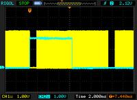
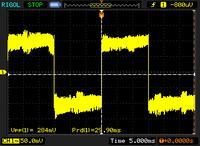
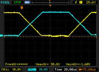
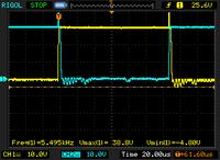
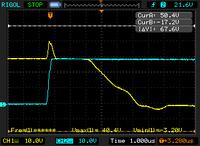
The Rigol revealed the LED was toggling 8 lines after the start of the frame & there was a 1.2ms vertical blanking interval, enough time that there must have been a point in the scanning where the LED could toggle without being split between 2 frames.
So turning the LED on at the beginning of the vertical blanking interval lined it up with the exposure for the 1st line, but caused it to light up the bottom half of the frames when it should have been off. The shutter seemed to expose 2 frames in the time taken to clock out 1 frame. To get in only 1 frame, the LED had to be on for only 1/2 the frame height.
This could be highly dependant on shutter speed & clockspeed, but it has to be done to get 35Hz position updates. This kind of raster line timing recalls the Commodore 64 days, where most any graphics required the software to do something when the CRT hit an exact raster line.
Synchronizing 2 cameras & moving data from a 2nd camera is the next great task. The easiest method is for each camera to stop its clock after each frame, then have the master camera issue a pulse to restart the clocks simultaneously. It would slow down the framerate & overexpose.
The only realistic way is to issue a pulse at the start of each frame & for the 2nd camera to constantly nudge its clock so its frame starts line up. The LED has to be so precisely aligned with the exposure, it doesn't leave much margin.
There's also forgetting about vision based distance & using sonar for the distance or using a large LED ring & a single camera.
Posted by Jack Crossfire |
Aug 30, 2012 @ 01:00 AM | 7,661 Views
As every flashing LED designer knows, you can't flash it in every other frame. It has to be toggled every 2 frames because the rolling shutter is always capturing somewhere between the frames. Trying to synchronize the flashing to wherever the rolling shutter is requires previous knowledge of where the LED is.
So the 70fps 320x240 is the only way, yielding only 17 position readouts per second. The webcam users are getting really degraded results.
There might be a way to recover position data from between the flashes. If every blob is accounted for in the last 4 frames, the frames are searched backwards in time for all the blobs in the vicinity of the blobs in the last frame. Blobs which disappear at some point going backwards are tagged. The largest is taken.
This would have a high error rate from false targets overwhelming the target when it just starts lighting up, before the target has grown to its maximum size.
The lowest error rate would come from only comparing the last of the 2 frames when the target is on to the last of the 2 frames when the target was off. Then, velocity data could be improved by comparing the known target in the last frame with any blob in its vicinity in the previous frame.
Posted by Jack Crossfire |
Aug 28, 2012 @ 11:50 PM | 7,469 Views
As suspected, downsampling with maximum instead of lowpass filtering made the LED stand out more. The problem was resolution. 88x96 wasn't going to give useful distance data. A solidly lit LED with multiple frames blended might improve the accuracy.
Analyzing the data on the microcontroller without compressing it can get it up to 320x240 70fps. 640x480 still only goes at 20fps. That definitely made you wonder what the point was of not using a webcam. Only the simplest algorithm can go at 70fps & it still takes a lot of optimization.
Accessing heap variables has emerged as a real bottleneck for GCC. Temporaries on the stack greatly speed up processing but create spagetti code.
The microcontroller thresholds the luminance & compresses the 0's. Works fine, as long as only the aircraft light crosses the threshold. A large bright area would make it explode. Compressing the 1's would take too many clockcycles.
The leading flashing LED algorithm begins with blob detection. Blobs which come within a certain distance of another blob in a certain number of sequential frames are considered always on & discarded. The largest of the blobs which don't have anything appear within a certain area in every frame is considered the target.
Posted by Jack Crossfire |
Aug 28, 2012 @ 12:27 AM | 7,436 Views
So got the TCM8230 to give 70fps by clocking it at 56Mhz & downsizing to 128x96. 56Mhz is the fastest the STM32F407 can do, according to the Rigol. Luckily, the Rigol was hacked to support 100Mhz.
Detecting the LED has emerged as the great task. If the camera moves, a flashing LED won't differentiate from the background. Movement of the flashing LED is already a difficult issue.
Hardware pixel binning seems to be no good. As the LED goes farther away, the intensity fades too fast. Maximum of nearest pixels is the only way. That makes the Centeye guaranteed to not work.
Posted by Jack Crossfire |
Aug 25, 2012 @ 11:16 PM | 7,892 Views
So vision has some options:
2 webcams, 2 isochranous competing USB streams, no control over exposure, no way to synchronize with a flashing LED, but full color 30fps 640x480. Doing this with the red/blue LED pair would work in a controlled environment, but not be a viable product. It would require a lot of wires & a USB hub.
2 board cams, daisychained wireless stream, full exposure control, at least 40fps 160x120 in greyscale.
The centeye may end up being the only useful one, because 2 can be scanned by a single chip. It does 112x112 greyscale with no onboard ADC. The wavelengths aren't given, but it probably does IR through visible.
It has a strange interface, which requires a bunch of pulses to set the row & column, then it clocks out a single row or column. There's no way to read a register. So the STM32F407 ADC goes at 1 megsample, but it would be drastically slowed by all the bit banging.
Min & max registers for the x & y, with automatic row increment would have gone a long way. Normal cameras have hardware windowing support & ADC's that run in the 40 megsample range. Microprocessors have hardware interfaces for normal cameras.
So the centeye would need an FPGA to make it look like a normal camera, before any useful speed could be had.
Trying to use a smaller window has been a house of pain. A 32x32 window can go in the hundreds of fps, maybe fast enough to track a point, but it's been done before with limited success. 60deg has been shown as the minimum viewing angle to track an object.
It also has pixel binning, which would slightly improve the framerate but not provide the required aliasing. For the right aliasing, the maximum of the pixels needs to be taken instead of the average. It may be that a high enough framerate, with a fast enough turret, can track a point with a 32x32 window.
Posted by Jack Crossfire |
Aug 24, 2012 @ 05:43 PM | 8,438 Views
Some more sonar ideas were scanning for a peak only within a few samples of the previous peak, finding the start of the peak by searching for the 1st positive derivative or the last point to exceed the maximum before the current peak. How would you find the last point to exceed the maximum? Some pings ware pretty nasty, with maximums set & dropped below. There were more diabolical pattern matching algorithms.
Nothing about sonar jumped out as bulletproof, while vision has already been proven in the dark. A simple test to separate a blinking LED from the background would seal it.
Ramped the sonar up to 60hz on the sending side, giving 20hz position solutions. Had the starts of pings detected from the derivative. When it was in a box directly over the ground array, it was actually very stable. The instant it got out of range, it died. It still didn't have the horizontal range, but the speed & accuracy required for stable flight were shown.
That was a lot of investment in electronics. It was the mane reason for the oscilloscope.
Posted by Jack Crossfire |
Aug 23, 2012 @ 09:37 PM | 9,300 Views
After all that work on making a high frequency amplifier, test flights once again led nowhere. It was definitely better than air to ground pings, but much less accurate.
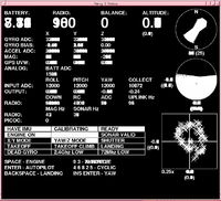
The latest thing is instead of recording & replaying telemetry files, making video of the ground station.
In 2007, you couldn't make video of a screen because AGP was unidirectional. That motivated a lot of investment in flight recordings. PCI express once again brought back the bidirectional speed to allow the screen to be recorded.
The most successful flight showed clear circling around the target position. The sonar successfully tracked it flying below 1 meter, in a 2x2 meter area, with 0.2 meter accuracy, but the feedback couldn't dampen the oscillation.
The sonar range is much less than air to ground. The omnidirectional motor noise is always near the airborne receiver, while it has a chance to diffuse before it hits a ground based receiver.
For confined, indoor use, sonar once again is best suited to a horizontal receiver array on the ground with an airborne transmitter that always points sideways to the array. It might still work for a monocopter, in which the aircraft has a couple pings per revolution which are always guaranteed to hit the ground array.
Going back to vision for daylight operations, Centeye is too expensive for any product, but a cheaper camera might be able to simulate the same high speed, low resolution magic trick, at a lower speed.
The idea with a low
...Continue Reading
Posted by Jack Crossfire |
Aug 22, 2012 @ 09:35 PM | 8,064 Views
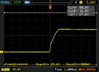
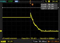
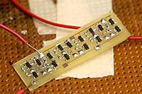
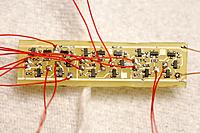
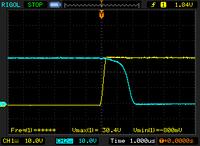
So the final transducer driver board came together. Got extremely short transition times & very loud pings. 30V transitions in 2us are 33% faster than the LF353, but getting short transitions is a very tempermental affair. The transition speed really does matter as much as the voltage, with these transducers.
There's an optimum ratio of current to drive the pullup & pulldown transistors in the h-bridge. Giving both transistors 0.3mA gives rise & fall times of 3us. Raising the pullup transistors to 3mA gives nanosecond rises, but lengthens the falls to 5us. Giving both transistors 3mA gets the rise to nanoseconds & the fall to 2us. So more current buys more speed, but only if the transistors are balanced.
The pulldown transistors have a hard job. They have to remove the charge built up on a capacitive speaker, but the speaker acts like a charge pump. When 1 pullup transistor starts, it tries pushing the 30V generated by the other one to 60V. In reality, it only gets to 40V before the transistor breakdown voltage stops it. That's causing a 40V spike & delay before the pulldown transistor starts removing charge.
There are ways to optimize it, controlling it with 4 GPIOs & staggering the transistors, using the charge pump effect to double the voltage. A career can be devoted to optimizing pings.
The Rigol resets to writing waveforms, every time it's rebooted. You have to remember to constantly set it to writing bitmaps, or nothing useful gets saved.
Also, 1 of the probes has already stopped working in 10x mode, so nothing over 30V can be measured. Reality of the $350 scope has definitely begun after only 1 week. Fortunately, anything with a BNC connector should work as a probe.
Posted by Jack Crossfire |
Aug 22, 2012 @ 02:59 AM | 7,836 Views
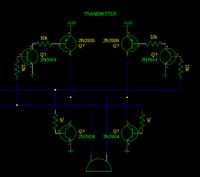
Yesterday's circuit failed catastrophically, because the voltage emitted by the NPN wasn't high enough to completely turn off the PNP. That was a lot of work.
There's a lot of rationale in building h-bridges instead of using an LF353 or high speed op-amp. The h-bridges can switch 3x faster than an LF353.
A few more ideas came along, to minimize transistor count. The trick is to use all NPN's, but they can't go all the way to the rails. While working at 12V, they died at 30V.
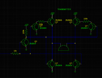
Finally gave up on component minimization & blasted the problem with a transistor mountain, still insisting the h-bridges should be controlled by 1 input & using an NPN to invert the control signal.
That failed miserably. While the rise time was a spectacular 1us, the fall time was longer than the world's worst op-amp at 100us. Virtually no power went to the speakers. It's unknown what killed it. It wasn't the inverting NPN. It wasn't the 100k resistors. The last suspect is shorting the bases of each push/pull pair of transistors to save on resistors.
Whatever the reason, the circuit is going to be replaced by LF353's. H bridges are impractical to mass produce. The LF353 can get 3us rises & falls for a lot less money. The wavelength is 41us, so the 2us difference shouldn't affect anything.
Today had many lessons.
#1 Working at 30V has a lot of traps for young players not present at 12V. 10k pullup resistors won't do. 30V across 10k is 0.1 W or 44% more than
...Continue Reading
Posted by Jack Crossfire |
Aug 21, 2012 @ 03:25 AM | 7,635 Views
Aren't you glad you didn't need to solder that board, but when an LF353 would either cost $20 or take 5 days to order, the easier option is some more epic analog BJT magic.
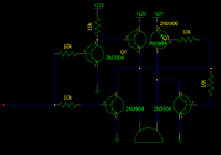
This one took a while to figure out. The object of the game was to make a comparator out of the fewest transistors. The trick was using the output of 1 side to drive the other side & using an NPN where a PNP would be used in an H bridge.
There was probably a magic search term which would have found the same thing on the goog.
So the next great hope is broadcasting pings from the ground to the aircraft. Initial tests with a single h-bridge driven transducer were promising. The trick is driving 3 transducers with a reasonable circuit, getting the aircraft to know which transducer is pinged & when, getting a ping rate high enough.
Posted by Jack Crossfire |
Aug 19, 2012 @ 02:37 AM | 8,098 Views
Among sonar methods, the most solid has a sideways emitter on the aircraft pointing directly at a sideways receiver array on the ground. The aircraft can't point towards any other direction & the altitude is limited to nearly the same height as the array. Totally worthless for an aerial camera, but this has the widest range of horizontal motion.
It might work on a monocopter, by pinging once for each revolution, when the emitter is pointing towards the array.
The next item was having the ground array transmit pings to the aircraft. The aircraft transducer receives less motor noise because it points away from the motor & is extremely directional. That gave a big improvement in low altitude noise rejection, but now 3 pings have to be created for each position solution, slowing the position sensing to 7Hz or 13Hz if you're lucky.
Each ground transducer needs either a real expensive op-amp or a real complex h-bridge. The oscilloscope finally revealed just how bad the LM324 was at driving a transducer. It was good enough for outputting very small 1 volt signals, but took 60us to go from 30V to 0V. That's 2/3 of the sonar wavelength. All those flights in 2009, with the LM324 driving pings at 10V weren't even close to full power.
To its credit, the op-amp has a hard job, outputting a precisely calculated voltage for a fixed gain. The h-bridge only knows on & off.
The good news is those are the only 2 contenders for sonar. Only the latter would be applicable to a monocopter.
Should note the oscilloscope brings a dream within reach, manely receiving the space station on a home made radio.
Posted by Jack Crossfire |
Aug 17, 2012 @ 11:20 PM | 7,846 Views
So the AHRS & attitude stabilization came together. The Blade CX is so unstable, it's amazing anyone can fly it manually. As predicted, the mane contentions were setting the 3 in 1 gyro gain, balancing it, aligning the IMU. Eventually, it was controllable for the computer with the same signals as the human interface. Fears of the low IMU frequency not handling the vibration were unfounded.
So either the machine noise or the downwash from the Blade CX killed sonar.
That was revealed by the year old PIC waveform recorder. The Rigol can't capture a long waveform.
Windscreens on the transducers did nothing, but it also depends on altitude. Changing the receiver gain did nothing, since motor noise is louder than the transducer when not head on.
This problem may be solved by putting the transducers on the ceiling & having the sender point up. The sender could also point straight ahead at a sideways array for testing.
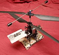
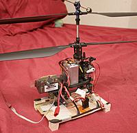
Hanging position sensors on the end of a long boom for a ceiling mounted system has now been validated by this award winning vehicle:

Posted by Jack Crossfire |
Aug 17, 2012 @ 12:38 AM | 7,598 Views
After very slow & methodical plugging of servos in, viewing all the voltages on the oscilloscope for surprises, all 4 PWMs were pulsing successfully. PWM could finally be measured precisely enough to do it without burning out servos.
The 1k resistors seemed to do the trick. It's very easy for a test probe in such a confined space to connect a PWM output to 30V.
Had yet another networking bug, in which another specific packet size was causing it to crash. The solution is to make all packets a known, good size. In none of the reappearances of this bug did a real solution emerge. Telemetry alone now goes at 90kbit/sec even though it only uses 20kbit/sec.
Armed with the I2C waveforms, the IMU slowness could now be tracked down to another pointer error instead of I2C interference. At 25Mhz, 3.3V, the PIC is now maxing out at 80 readings/sec from lack of clockcycles.
Finally, the oscilloscope revealed 2 strange behaviors in the 3 in 1 motor controller. The throttle & yaw pulses must be staggered or it reads all yaw as full left. Yaw must be pulsed in order to shut down the motors. If just throttle is pulsed at cutoff level, it'll never shut down.
Motor control issues being resolved leaves extreme drifting in the IDG3200 IMU, calibrating the E-flite rate gyro without a stick controller, calibrating attitude stabilization, automatic cyclic, full automatic.
A traditional coaxial copter, with its multitude of different PWM waveforms, vibration, &
...Continue Reading
Posted by Jack Crossfire |
Aug 16, 2012 @ 02:35 AM | 7,694 Views
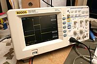
After 20 years of electronics in the dark, an oscilloscope finally materialized on the bench. It's the legendary Rigol DS1052E, overclocked to 100Mhz. The mysteries of I2C & sonar problems could now be revealed. The rise time on I2C is extremely slow & is what's limiting the bandwidth. There's no obvious RF interference.
The sonar voltage very precisely matched its predicted shape, but there's a spike to 40V.
The next board came together, immediately revealing the dual LM317 scheme is still not enough. There needs to be yet another offboard TO-220 hack. Never figured out what fried the last chip. Just put 1k on all the PWM outputs & delayed the airframe integration to think of more ideas. Never giving up, the board has the footprint for a TCM8230 camera.
The 30V sonar voltage is actually present on the transducer case. If any of it conducts through balsa or the transducer contacts a servo pin, it could explode.
Posted by Jack Crossfire |
Aug 15, 2012 @ 01:48 AM | 8,460 Views
So with everything buttoned up, plugged the battery in, the servos seized up, & unplugged the battery. The servos are not pulsed at this stage. Only floating inputs could have done that.
Plugged it in without the servos & got sporadic crashes & bogus DC voltages from the PWM outputs. 1 motor would spin, but not the other, regardless of yaw. Then, noticed the ARM was getting hot, rebooting, & dying. Somewhere during the fabrication, the ARM got damaged. Yaw PWM was showing ground. Roll servo was showing 2.5V. Pitch servo was proper PWM.
The only logical explanation is some funny business with the PWM wires. Maybe they have transient connections to 8V. Maybe they have to be connected through resistors.
Posted by Jack Crossfire |
Aug 14, 2012 @ 02:16 AM | 7,805 Views
The TCM8240 was finally voted off the island, when it showed a sporatic short circuit which caused the CPU to die. Maybe that was making it fail to output raw data.
The closest it came to outputing anything was using the registers found on:
https://forum.sparkfun.com/viewtopic...0314&start=180
It only produced a completely white picture. Maybe the chip was defective. Maybe the pinout had an error. It doesn't matter, since it never encoded JPEG & there is a much smaller camera which can output raw.
Also remembered 1 way to simplify the routing & shrink the board is to connect the data pins out of order, then use a software lookup table to reorder the bits. Who knows how slow that would be. A speed test on the revision 1 board would reveal the impact, but be a lot of work.
The PWM signals are being generated. The IMU is being read & fused. Time to put it on the airframe.
Posted by Jack Crossfire |
Aug 13, 2012 @ 03:32 AM | 7,765 Views
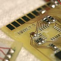
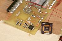
So that's the traveling exhibit. Marcy 2 underwent 2 board designs to support 2 different cameras. After 3 days fighting it, the TCM8240 finally won & no picture could be gotten from it. There wasn't enough documentation to get either JPEG or RAW.
There was a brief fascination with getting the TCM8240 to work in any RAW mode, once JPEG was proven unworkable, but without JPEG, it's absolutely worthless & too heavy to justify buying any more of.
In 1280x1024 mode, the scan rate would be so slow, it could only photograph stationary objects. No-one is going to invest in an SRAM if cheap spycams can get higher resolution. Finally, the TCM8240 overheated the power supply.
With single layer home made etching, the TCM8240 board can't be reconfigured at all to use the TCM8230. Rerouting is only feasible with the arrangement on the TCM8230 board. It needs to get a lot bigger to support sonar.
If the TCM8240 worked, it would have been a wifi video downlink from the Blade CX. It would have been neat, but the Blade CX is going to a customer, never to be seen again.
It got me thinking the monocopter is extremely limited. It could only be used for low resolution still photos, but nothing useful. The neatness of 4fps video from a spinning wing quickly fades when considering the usefulness of video from a stationary copter. Something that automatically follows your face would be useful for a low end video blog.
Both platforms are aerial, so always very shaky compared to a ground based camera robot, but still ahead of most content. Anything aerial would be better suited to still photos. Part of the motivation to fight for shaky, low res video on a copter that's going away, with a camera that's going away, was to keep the $60 spent on those from being a mistake.
Posted by Jack Crossfire |
Aug 12, 2012 @ 12:25 AM | 7,937 Views
The time finally came to integrate another flight computer on another airframe. The IMU is limited to 60Hz, because of the wifi interfering with i2c.
I2C on the IMU can handle 29khz. At 30khz, the wifi kills it. An oscilloscope would show what's happening & probably reveal a solution, but lacking the budget, the IMU speed has to be stuck.
I2C in burst mode is an alternative way, but it has never worked.
Also spent a few hours on the TCM8240. The JPEG output seems to have a valid header & start codes, but its compressed image data is all repeating patterns which the decompressor can't read.
Here the 0xffda code for the data segment is followed by a repeating pattern.
Code:
30    e5 e6 e7 e8 e9 ea f2 f3 f4 f5 f6 f7 f8 f9 fa ff     ................
40    da 00 0c 03 01 00 02 11 03 11 00 3f 00 af 45 00     ...........?..E.
50    14 50 01 45 00 14 50 01 45 00 14 50 01 45 00 14     .P.E..P.E..P.E..
60    50 01 45 00 14 50 01 45 00 14 50 01 45 00 14 50     P.E..P.E..P.E..P
70    01 45 00 14 50 01 45 00 14 50 01 45 00 14 50 01     .E..P.E..P.E..P.
80    45 00 14 50 01 45 00 14 50 01 45 00 14 50 01 45     E..P.E..P.E..P.E
90    00 14 50 01 45 00 14 50 01 45 00 14 50 01 45 00     ..P.E..P.E..P.E.
a0    14 50 01 45 00 14 50 01 45 00 14 50 01 45 00 14     .P.E..P.E..P.E..
b0    50 01 45 00 14 50 01 45 00 14 50 01 45 00 14 50     P.E..P.E..P.E..P
c0    01 45 00 14 50 01 45 00 14 50 01 45 00 14 50 01     .E..P.E..P.E..P.
Posted by Jack Crossfire |
Aug 11, 2012 @ 04:47 AM | 7,351 Views
With the 168Mhz ARM, full IMU, & JPEG camera, the hackneyed power supply is maxed out. Now a real bench power supply with current limiting is looking real good. You need current limiting to handle accidental battery connections into the power supply. With 30V sonar, it's going to be sucking serious power.
A quick IMU to handle the newly discovered instability came together. It updates at only 50Hz. The theory was there is so much interference between wifi & i2c, the IMU would use a PIC to read all the i2c sensors locally, then encode the results on a UART for the long wires to the ARM.
Like the ARM, the PIC i2c bus maxed out at 24khz before wifi started interfering. That only gave 50Hz updates. It could double it with parallel i2c busses for the accelerometer & gyro, but those are no longer made in separate chips. It would be a 1 off board. Have a feeling, if there's time left over, parallel i2c busses are coming anyway.
The PIC needs 16Mhz to get 50Hz updates.
Time for another stab at downlinking the JPEG video & then some AHRS solutions.
Posted by Jack Crossfire |
Aug 10, 2012 @ 12:17 AM | 6,284 Views
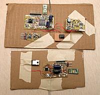
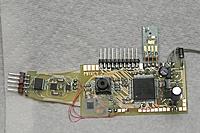
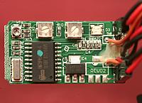
So decided to bring up the TCM8240 on the latest board. Decided to use the same board for Marcy 2 & the Blade CX II. It's a lot of work to lay out a new board for each aircraft. They would both use the magnetometer & possibly camera.
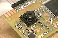
Got it spitting out JPEG images at theoretically 1280x960. There is hope it can compress 640x480 in addition to the full 1280x1024. The mane issues with the TCM8240 are:
The pins are ridiculously close together, since it was obviously a surplus item intended for another product. If anything bridges, you need to desolder it & try again.
Pulse reset after power up.
PLL must be enabled for JPEG to work. Set register 0x3 to 0xc1.
Enable the data output & JPEG compression by setting register 0x4 to 0x40.
Data automatically starts streaming from the pins.
The day was spent remembering to call DCMI_CaptureCmd(ENABLE); to begin capturing on the STM32F407.
Thought this camera streaming wirelessly would make a good demo during an interview. Helas, another interview never happened, as someone else with just the right buzzword came along.
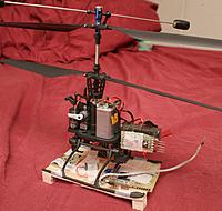
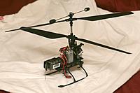
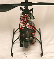
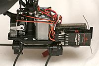
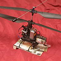
Then came the Blade CX II. Passed up any newer quad or flybarless copter in favor of this, because it was believed to be the most passively stable, it had the smallest size for its payload, & coaxials used to dominate academic research before quads.
For all the hype about coaxials being super stable, fuggedaboudit. It was extremely unstable & hands on to stay in position. To be sure, the tail undoubtedly stabilized the yaw & balanced it more, but there's no way that level of sensitivity is always going to be satisfied.
Marcy 1 is extremely stable. She can lift off & hover with no cyclic input. That kind of stability is way beyond anything commercially available.
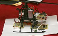
The good news about the blade is the radio & flight computer were separate boards, making radio replacement easy. The payload should be plenty to handle the new flight computer.
 Views: 308
  Views: 270
  Views: 270
  Views: 252
  Views: 268
  Views: 258
  Views: 325
  Views: 305
  Views: 342
  Views: 298
  Views: 302
  Views: 257
  Views: 272
  Views: 269
  Views: 251
  Views: 266
