Posted by Jack Crossfire |
Nov 30, 2012 @ 02:39 AM | 7,967 Views
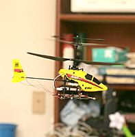
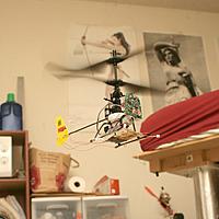
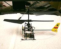
After all that work, the Blade MCX was stable enough for a video. The limit in accuracy of a pan/tilt camera has probably been reached. The next step is to refill the tires, get soaked in the rain, & take it all to a larger room, to fly waypoints.
Pan/tilt vision tracking has been in use for 18 months. Its weaknesses are now known. It was a good way to fly a very stable monocopter, but hasn't been great with more unstable copters.
Except for monocopters, a common theme has been vehicles which are extremely stable being hard for the machine to fly. Though normally passively stable, they have occasional slips which the quick responsiveness of a human can dampen but a machine tuned to very minor feedback can't.
Posted by Jack Crossfire |
Nov 28, 2012 @ 09:53 PM | 8,276 Views
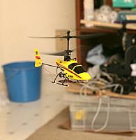
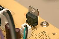
Finally got it to where it could drain an entire battery in a hover. It only lasts around 2 minutes. The IR leds consume enough power to make the voltage regulator hot.
The Edmond Optics IR filter ended up necessary. The higher shutter speed it requires got the framerate up to 30. The floppy disk required a shutter speed that was too slow to get 30fps. Some more software optimization got the position sensing good enough to do it.
It was entirely a matter of improving the position sensing speed. A pan/tilt camera using PWM to estimate the pan/tilt angles for every frame is going to max out in a 2m hover radius. It basically needs all the empty space in the room to hover.
Posted by Jack Crossfire |
Nov 28, 2012 @ 02:54 AM | 8,063 Views
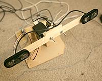
So the servocity mount was voted off the island. With all the requirements for sensing its position, it was too slow. After PWM recalibration & a voltage experiment, the home made mount came back.
Another attempt to slow it down by running it on 3.3V made the motors stall. Tower hobbies said it ran on 3.3V. It must have been rediscovered many times but lost to memory that 3.3V makes it stall.
Then, the task of aircraft tuning resumed. There is a lot of noise in the position sensing, but given enough balancing, it can fly itself for a short time. Without a very good position readout, the feedback needs to be bare minimum & the balancing needs to be exact. The IR cameras only do 20fps while the visible cameras did 34fps, making for a much slower position reading.
The Syma X1 was more forgiving of balancing, but the Blade MCX is the vehicle of choice for micro UAVs because it is the smallest with full cyclic yet has the highest payload for its size.
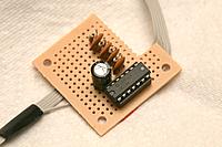
Ended up putting a follower amplifier on the digital to analog converter, to eliminate any chance of the rc transmitter failing to receive the right voltage. That turned out to not be the problem.
Posted by Jack Crossfire |
Nov 26, 2012 @ 10:24 PM | 7,675 Views
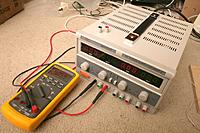
This thing arrived. It's big, heavy, linear & expensive. $180 for 2 variable outputs & a 5V fixed output. It doesn't give the settings without being on. To test a new circuit, you could short the outputs to calibrate the maximum current. In reality, you'll turn the current to maximum, turn the voltage to minimum, & slowly ramp up the voltage.
Posted by Jack Crossfire |
Nov 26, 2012 @ 02:56 AM | 7,705 Views
The $350 camera mount lives, for now. With PWM as the only position estimation, the servo movement has to be extremely slow or it oscillates, but it's already built up. The cheap mount had servo wobble which equaled the position inaccuracy of the expensive mount, but speed may still bust the $350 camera mount.
Now comes intensive balancing. A slight PWM adjustment & the Blade MCX lifted off with the electronics. It barely has enough power to do it before maxing out the motors & going into a left yaw.
Posted by Jack Crossfire |
Nov 25, 2012 @ 03:06 AM | 8,134 Views
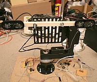
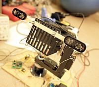
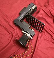
It looks like the PT785-S Pan & Tilt System is getting voted off the island. It's perfect for smooth motion of a manually controlled camera to rough positions, but the application here is automated motion control to precisely reproducible positions, which it can't do.
It returns to a very rough position & can't return to the same position if manually pushed out of position or restarted. Using either an IMU or the raw pot voltages to detect the position was worse than just using the PWM values, so the position readout eventually used the PWM values & accepted any discrepancies in the translated position.
The only advantage it had was very smooth motion, but the pointing errors were bigger than any jerkiness in the motion of a servo. Developing a precisely reproducible motion control platform is a full time job for a 6 month timescale & all this investment in squeezing the last bit of accuracy out of robotics probably isn't worth as much as making a good tablet interface.
Posted by Jack Crossfire |
Nov 24, 2012 @ 11:48 PM | 7,928 Views
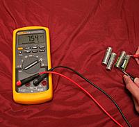
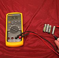
The quest for powering the 580EX II revealed only 1 of its 4 lithium cells actually died. Testing the voltage of all of them instead of just 1 revealed 1 cell had 1.3V while the others had 1.4V. But the new trick was measuring current. The 1.3V cell had 0 current. Didn't measure the 1.4V cells. Not sure how much a fully charged lithium cell would generate.
The 580EX II was powered by a single set of NiMH's ever since it arrived in April 2008. It very quickly showed it wouldn't work with anything but brand new batteries, yet new & old batteries showed the same voltage. The same 4 NiMH's made the only photographs of M.M. in 2010 & suddenly stopped working with the flash in Sep 2012.
The Fluke 87V finally revealed why. Their ability to provide current decreases with age. Fully shorting a new NiMH gives 7A while a 4 year old NiMH only gives 1A. The flash needs 7A while a mouse can get by on only 1A. Don't try this with a Lipo. There are ways of doing it with a resistor.
Posted by Jack Crossfire |
Nov 24, 2012 @ 04:40 AM | 7,524 Views
That was amusing. The $30 filter either has a wider pass band or less attenuation than the floppy disk. You can layer the filter or just whack a single floppy disk layer on. The camera lenses have a finite number of filter swaps before their focus has to be redone.
The guy mentioned the floppy disk was merely attenuating the entire spectrum instead of selecting for IR, while the $30 filter was selecting for IR. If that was true, a bright white LED would show through the floppy disk, but it doesn't. Only a red LED shows.
Also, looking through the floppy & the $30 filter with the naked eye shows the same pass band, with slightly more light passed through the $30 filter.
Posted by Jack Crossfire |
Nov 22, 2012 @ 05:05 AM | 7,749 Views
An el cheapo $30 5x7" sheet of IR filter arrived from edmondoptics.com. With the naked eye, the view looks exactly the same as through a floppy disk. The problem is of all the DIY IR filters on the internets, none is made of something still in production. Floppy disks & film are no longer made.
It breaks apart like glass & hot glues on the lens easily. It seems to be common charcoal baked into acryllic plastic.
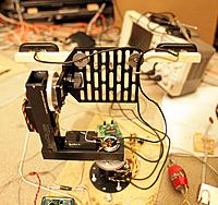
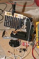
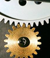
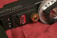
Next, the next camera mount was fully assembled & powered up with PWM. Be sure to keep the cables clear of the gears. The gears chew them up, instantly. If you accidentally turn it more than 180' & shift the center point of the pots, turn it the opposite way more than 360' until the pots are reset.
Also, discovered PWM above a certain point causes the servos to spin forever.
Another hack to use direct pot readings has given much better accuracy than an IMU. Other than motor magnets, it's hard to understand why the IMU was so inaccurate & was so hard to calibrate. The iPAD IMU gives very accurate compass headings with very little calibration. It may just be inaccurate alignment of the accelerometer & magnetometer.
The amount of energy devoted just to building up yet another camera mount brings the sensation of going in circles. This is the 3rd unique camera mount built since Summer 2011.
They only exist because someone else is paying for them, there needs to be 1 here for testing while he brings another on travels.
...Continue Reading
Posted by Jack Crossfire |
Nov 21, 2012 @ 04:39 AM | 7,397 Views
So after all its calibration, the IMU on the camera mount was not accurate enough to improve camera pointing. Magnetic heading was always slightly off & required very precise calibration. It may have been magnetism from the servos. That led back to hacking into the servo pots.
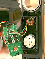
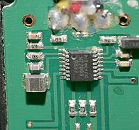
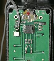
The only way inside the winch servos was to desolder the motors. That revealed the pot was indeed exposed on the outside, but undetected due to a probing error. Those $50 winch servos have some beefy MOSFETs & a big motor. $50 buys a lot more than $10.
While staring at this $50 servo's crumbling lead free soldering with no conformal coating, it should be noted that it's no good for a mission critical aerospace application. The soldering is going to have tin whiskers.
The servos only use 1V of the full range of the pots. They leave a 1V buffer on each end. This seems to be because of the strange behavior of the pots. They don't have upper & lower stop points.
With no PWM, they can be manually spun beyond the maximum revolutions, using some kind of slip ring, then wherever they reverse direction becomes the new boundary. The servos have the 1V buffer to avoid changing their center points.
Of course, this means the center point changes depending on how the camera mount is rotated when it's off. The easiest solution is to put mechanical stoppers in the mount to stop it from rotating beyond the boundaries.
Posted by Jack Crossfire |
Nov 20, 2012 @ 05:43 AM | 7,682 Views
The answer is no. The motor in this $50 servo can't be pulled out without damaging it. Maybe the motor terminals can be soldered to some wire to apply more force to it. Those right angle traces are things you don't see every day.
Using the servo pots to detect where they're pointed would be nearly as accurate as an IMU for determining camera angle.
The IMU for camera pointing is a buster to implement & configure, but it is the most accurate measuring device. It would eliminate all methods besides PWM if it didn't improve the accuracy.
The process of integrating the IMU & ground station on the camera mount is long & hard. Future soldering & development has to be done on the floor, with a portable iron & laptop. The quest for an ideal bench has never yielded anything. Eevblog seems to have the ideal bench for electronics, but not for a computer.
Posted by Jack Crossfire |
Nov 19, 2012 @ 06:26 AM | 10,925 Views
Then there was the MPU9150. A day of banging on it revealed this: it's an MPU6050 & AKM8975 in the same package & connected by the same I2C wires. To actually see the AKM8975 on the I2C bus, page 28 of the product spec says enable pass-through mode, but doesn't name any registers. Page 30 of the register map says INT_PIN_CFG has a I2C_BYPASS_EN bit, which sounds right, but setting I2C_BYPASS_EN didn't work.
The ES_DA & ESCL pins ended up soldered to the MCU_SCL & MCU_SDA pins before the AKM8975 appeared. It didn't help either that every datasheet & every schematic had different labels for the pins. At least the MPU9150 demo board only required VDD, GND, SCL, & SDA.
Next, the AKM8975 read out perfectly, but the accelerometer showed only 0. Enabling the highpass filter did nothing. Together with the lack of a functioning I2C_BYPASS_EN bit or any interrupt enable bits, it appeared the accelerometer wasn't turned on.
There was also some research in the DMP firmware. It apparently was a science project to get it to work. It required many calibration constants written by many I2C writes, uploading firmware over I2C, a highly restrictive license. The Invensense ARM board used to demo it required a Windows program with proprietary USB protocol, nothing that would run on a rasberry pi in the field. It was hardly the cut & dried interface found in a speech synthesizer chip.
Since the project is only a 1 off demo to be discarded, the MPU9150
...Continue Reading
Posted by Jack Crossfire |
Nov 18, 2012 @ 06:07 PM | 7,367 Views
So the 18f14k50 in use since 2009 had yet another silicon error where PORTA 0:1 couldn't be read unless the IOCA bits were set. Also, the pullups on 0:1 don't work. This is why microcontrollers get standardized on for years, until they're either discontinued or become useless for the application. There are always a myriad of errors to be discovered.
Next, discovered the Rigol samples at 500megsamples/sec in long memory mode, but 1gigsamples/sec in short memory mode. Nothing has required that fidelity & the probes probably can't do it either, but now you know.
Finally, the quest to power the Canon 580EXII never ends. Lithium batteries only lasted 2 months. There seems to be no reliable solution besides AC power.
The servocity pan/tilt module is so slow, it requires an IMU to know where the camera is pointed in each frame. The mighty MPU-9150 is set to do this. There are horror stories about the licensing of its firmware where Invensense charges an outrageous fee to sell a product which actually uses their product.
At least a supply of AKM8975's was located, providing a stop gap solution to the magnetometer issue. The limits of weight, size, update rate, & power supplies make finding the right magnetometer very involved. The AKM8975 is the only one which has fit in the requirements of a microscopic vehicle.
Posted by Jack Crossfire |
Nov 17, 2012 @ 02:30 AM | 7,572 Views
It's an extremely heavy duty machined, high quality camera mount. It has potential mounted on a heavy duty tripod for making panoramas, but it's not precise enough to make timelapses or aim a telescope.
After some shock at the lack of potentiometers for determining the angles, it turned out the servos are multi-turn winch servos & the gears are designed to convert the complete range of the servos to exactly 1 360' turn.
They take the standard 50Hz 1ms-2ms servo PWM. The servos turn quite slowly & there's a long delay, which means you'll need an IMU to know where it's pointed at any instant.
The $50 dual servo controller saves time in figuring out the protocol, but does nothing but generate PWM. There's no feedback from onboard position sensors. It has no voltage regulator.
Most of the cost goes to having it made in a strange country.
Posted by Jack Crossfire |
Nov 16, 2012 @ 08:02 PM | 7,385 Views
It's no longer made & like most modern parts, only had a 3 month manufacturing run. It was ordered long ago. You collect enough to build a single run of your product, write the driver as fast as possible, & don't plan on using it anymore.
It's really hard to get working. 1st, the internal pullups aren't good enough to run it higher than 10Hz. It needs external pullups for any useful rate.
2nd, it requires SCK to be low during all SDA transitions. Most I2C devices let you get away with changing SDA while raising SCK.
3rd, the required voltage stability is insane. It needs under 50mA voltage ripple on DVDD & AVDD. The tolerance is slightly higher on AVDD. If AVDD is too unstable, I2C doesn't work at all. If DVDD is too unstable, it doesn't take any readings. To coexist with the 900Mhz radio & aircraft noise, it's going to take a serious, heavy LRC circuit & possibly a LDO regulator.
Despite all this, the only time it worked was when powered directly from an active 3.3V regulator. Powering it with a resistor or diode didn't work.
The update rate has been really slow. The 50Hz rating is optimistic. 10Hz is more realistic for any of the register settings.
It's probably going to end up replaced by a MAG3110FCR1, but the driver is written & working.
Also, it took 1 day to get the radio to work on the Marcy 3 board, even though it was the exact same layout as Marcy 1. It was an untested software change & the fact that full duplex is extremely complicated.
Posted by Jack Crossfire |
Nov 15, 2012 @ 04:45 AM | 7,936 Views
This return to webcams brings back nostalgia for the 1st webcam, the one which proved vision based flying was possible. The 1st webcam arrived in June 2011, after a run to Office Depot, a spontaneous purchasing decision & a freak sale that lowered it to $40. It now costs $54.
M.M. was not only still around back then, but had 1 month of residency left in this area, all to be spent with the 1 man She loved more than everything. Creative output was a lot higher, back then.
One must look at where one lives & decide if making an irrational move isn't justified by an increase in productivity. There's no economic force keeping a move from happening. A move to Simi Valley would increase productivity to where it was in 2011, no matter how irrational it was.
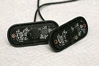
Anyways, unlike 2011, the webcams are now used exclusively in IR mode. Fortunately, they haven't miniaturized webcams to the point of being impossible to convert to IR. It's inevitably going to happen, since the number of microscopic phone cams outnumbers the number of webcams.
Posted by Jack Crossfire |
Nov 14, 2012 @ 04:07 AM | 7,637 Views
Initial tests with the IR converted webcam were promising. It very nicely separates the IR led from an LCD monitor, ambient light, but not lightbulbs. The failure to convert the board cam but success of the webcam means no flashing is possible, but this eliminates the weight of an IR receiver. Still think the LED flashers using webcams are settling for a really slow update rate.
The IR led runs at 1.2V & 40mA. A 3.7V lipo gives a useful voltage to 3 IR leds in series. A 100R resistor powers 1 on 3.3V. In the worst case, 2 in series can be PWMed based on battery voltage. The need to maximize the brightness makes that most likely.
There's a slight chance a chroma key & comparison of neighboring blobs might eliminate lightbulbs. They would appear as a ring of red with white in the middle. The LED target would appear as a ring of blue with white in the middle. Eliminating blobs with neighboring red might work. Also, if multiple blobs are visible in the luma key, it could calculate the amount of red & blue in each blob, then take the blob with the most blue.
Otherwise, it's the same game of pointing all lightbulbs away from the camera & avoiding windows. Eliminating flashing should give faster updates. IR should also be the key to making Marcy 1 fly with the lights on.
The webcam reality makes it unlikely that the rasberry pi would be fast enough. There's going to be JPEG decompression at 640x480, which is a lot slower than RLE at 640x240.
...Continue Reading
Posted by Jack Crossfire |
Nov 13, 2012 @ 02:38 AM | 8,092 Views
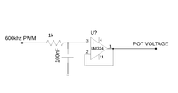
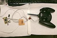
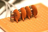
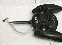
For this one, a 100nF, 1k RC network filtered a 600khz PWM to generate the stick voltages. That produces DC voltage changes well over 100Hz without serious ripple. It doesn't work with the controller off, since the stick voltages end up powering the micro. With it on, it works. The flight software has to be running & generating a 0 throttle voltage before the controller can be powered up. Finally, the copter can be powered up.
Throttle & pitch are 0 for full down to 3.5V for full up. The PWM only gets it to 3.2V. A voltage regulator trimming could get it to 3.5V. Roll & yaw are 0 for full right to 3.5V for full left.
It's always unknown if these controllers can be hacked. They might have logarithmic pots or require an exotic voltage. What makes this system run on steroids is the use of a 900Mhz radio in full duplex to get extra telemetry.
Posted by Jack Crossfire |
Nov 12, 2012 @ 10:19 PM | 7,987 Views
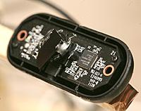
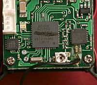
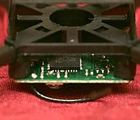
After the Blade MQX & Syma X1 micro quads having nothing but gyros, it was surprising again to find the Ladybird had accelerometer. A freescale MMA8452, to be exact. It doesn't do a very good job remembering what level is, but it dampens its own motion. It's further evidence of the propeller inertia being related to the self leveling.
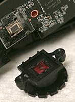
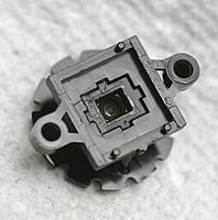
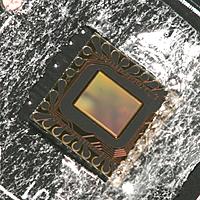
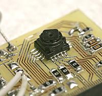
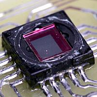
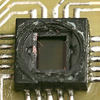
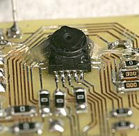
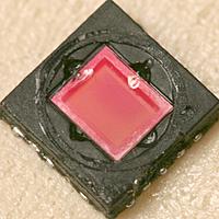
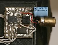
The mane event was the planned conversion of the TCM8230 to IR. Unlike the webcam conversions described on Google, its IR filter is integrated with the sensor & turned out to be aggressively glued in place.
Using an xacto knife to pry off 1 filter ended up crushing the filter & scratching the sensor. That bridged the power rails & it burned out after powering up.
Heating a 2nd sensor with hot air while prying off its filter with a T pin ended up scratching the sensor again. It requires too much force to pry off.
With $20 of an end of life camera destroyed, conversion of the TCM8230 to IR was busted. IR video definitely requires a webcam with a large filter attached to the lens instead of a tiny filter attached to the sensor. That rules out manual exposure, synchronizing a flashing LED with each frame, or processing the video on a microcontroller.
Since all the image processing was heading towards a rasberry pi, there was less incentive to bother with a board cam. The wifi glitches meant all processing had to be done on a rasberry pi instead of a tablet.
The board cam could always stick with visible light.
...Continue Reading
Posted by Jack Crossfire |
Nov 12, 2012 @ 04:13 AM | 7,676 Views
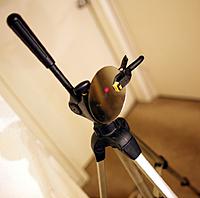
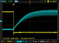
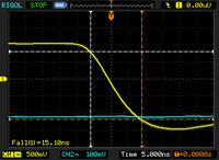
So ya wanna measure distance with 4 cheap radios & a cheap SRAM to measure propagation delay. Before investing in a full system, let's try it with a laser reflection & a Rigol.
A cheap radio would have automatic gain control & might have less capacitance, but the problems of longer rise time with a smaller signal & erratic half way point in the waveform would probably still be too great. Maybe a very low resistance pulling down the photodiode & a very high amplification would get rid of enough capacitance.
The kind of components it would take to measure propagation delay of RF are going to be out of reach, for any human price scale. You'd think someone would invent a local area GPS system, which used a different frequency, but used the same components to have a cheap GPS system in a room.
Another idea was to hack a laser tape measure to use a radio for part of the signal propagation. The same problems of capacitance & erratic rise time would apply.
The schedule is now to convert 1 aircraft to autopilot every month, combined with several days of formalities required to run a business: symbolic meetings & symbolic traveling. It's extremely ambitious & doesn't leave any time for experimenting. At least the Blade MCX came through as a viable platform, right away, & the method of overriding the controls is proven.
...Continue Reading
 Views: 199
  Views: 180
  Views: 174
  Views: 163
  Views: 170
  Views: 163
  Views: 167
  Views: 175

