Posted by crteensy |
Feb 16, 2020 @ 08:50 AM | 9,056 Views
The first iteration of my first ESC is described here: https://www.rcgroups.com/forums/show...a-BLHeli_S-ESC
and while I'm slowly beginning to call that done for now, I'll go into the second interation to get rid of some FETs I used for level shifting the gate driver inputs from 3V3 to 5V. Those FETs are Q1, Q3 and Q5 (DMN2990UDJ) in the previous design. They are tiny, but still about 1 mm� each. That's 12 mm� and easier routing on a 4in1 ESC, and that's something!
New schematic:
ESC_v0.4_single.pdf
The pinout is that of "O", as is the basic function of each output, but they have to be open drain and inverted with regard to original "O". A prototype of the driver stage is already built - the PCB is the same as before, but without the EFM8BB2 (that's on its own little breakout board) and without the level shifter FETs, plus some magnet wire.
Comments (4)
Add Comment
Posted by crteensy |
Jan 01, 2020 @ 03:14 PM | 18,666 Views
So here's my first attempt at building a BLHeli_S ESC. The current hardware is made for testing the overall circuit and part choice; the overall goal is a small and lightweight AIO FC.
I'm not sure what the max current will be, but anything above 10 A would be a good start. Battery input: 1 - 3S, maybe 4S.
5V and 3V3 rails are supplied with a TPS630701 buck/boost regulator for 5V and a TPS62823 regulator for 3V3. Those two seem to work.
Schematic: ESC-0.3-single.pdf <- THIS SCHEMATIC CONTAINS AN ERROR: Ac/Ap, Bc/Bp and Cc/Cp are swapped.
Apparently fixed schematic in https://www.rcgroups.com/forums/show...6#post43810839
Most parts were chosen for their small size. The NCP81253 gate driver is just 2x2 mm, but needs 5 V logic. There's a level shifter in front, built with a DMN2990UDJ-7 and two resistors. The gate driver drives a SIZ322DT NFET pair.
Here's a screenshot of one channel (and it contains the same error as the first schematic above):
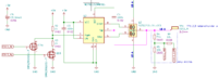
When the gate driver's PWM input is around 2.5 V, it will disable both out FETs.
Here's a logic table for the Ac and Ap signals with their effect on the output:
The last two columns are labeled PFET and NFET because the level shifter logic makes the whole gate driver look like a pair of PFET and NFET to the MCU. As far as I understand it, O-type firmware should work for this.
Top Layer Silk Screen for...Continue Reading
I'm not sure what the max current will be, but anything above 10 A would be a good start. Battery input: 1 - 3S, maybe 4S.
5V and 3V3 rails are supplied with a TPS630701 buck/boost regulator for 5V and a TPS62823 regulator for 3V3. Those two seem to work.
Schematic: ESC-0.3-single.pdf <- THIS SCHEMATIC CONTAINS AN ERROR: Ac/Ap, Bc/Bp and Cc/Cp are swapped.
Apparently fixed schematic in https://www.rcgroups.com/forums/show...6#post43810839
Most parts were chosen for their small size. The NCP81253 gate driver is just 2x2 mm, but needs 5 V logic. There's a level shifter in front, built with a DMN2990UDJ-7 and two resistors. The gate driver drives a SIZ322DT NFET pair.
Here's a screenshot of one channel (and it contains the same error as the first schematic above):
When the gate driver's PWM input is around 2.5 V, it will disable both out FETs.
Here's a logic table for the Ac and Ap signals with their effect on the output:
Code:
    Ac Ap PWM PFET NFET
1)  0  1  2V5 off  off
2)  1  1  0V  off  on
3)  0  0  5V  on   off
4)  1  0  0V  off  on
Top Layer Silk Screen for...Continue Reading
Posted by crteensy |
Aug 26, 2019 @ 02:45 PM | 8,459 Views
Here's pack #8:
Power loops apparently aren't boring yet and I need to remember to go into air mode right from the start. I do like non-air for landing though, even if my landings are still crappy (as are my turns). Overall I'm happy with the progress and feeling much more comfortable than during pack #1.
| FPV progress - flight #8 (3 min 42 sec) |
Power loops apparently aren't boring yet and I need to remember to go into air mode right from the start. I do like non-air for landing though, even if my landings are still crappy (as are my turns). Overall I'm happy with the progress and feeling much more comfortable than during pack #1.
Posted by crteensy |
Aug 23, 2019 @ 04:11 PM | 7,746 Views
After I had some Rx losses in packs 4 and 5, I decided to install an R9 Rx instead. Actually, in flight #4, the OSD shows an RSSI of 0 mid flight (that's with the R-XSR I had installed before). Packs 6 and 7 didn't show any sign of low RSSI or even Rx loss any more, but it's too early to really count on that.
Also in pack #4 I had some unwanted trim on the pitch axis. All trims are removed now and not having to fight that constant back spin is much better.
I'm now trying to launch in such a way that the quad immediately goes forward after taking off, by applying a bit of throttle and leaning forward before I take off. Seems to work.
Theses two packs were fun to fly although I had to stay on one side of the RC field, but watching the flights is probably not much of a thrill.
Here's #6:
Chasing a jet that is just about to touch down wasn't that much of an accomplishment, but the other one was fun.
Throttle is scaled to 85% but still a bit tough on the battery I guess. The logs show sag down to 9.1 V (for a 3S pack) at about 60 Amps in those power loops. That's just above the peak C rating of the battery (BetaFPV 3S 850 mAh 35C/70C). I'm looking for smaller motors now, but then again I could simply build a smaller 3" quad instead.
And #7:
...Continue Reading
Also in pack #4 I had some unwanted trim on the pitch axis. All trims are removed now and not having to fight that constant back spin is much better.
I'm now trying to launch in such a way that the quad immediately goes forward after taking off, by applying a bit of throttle and leaning forward before I take off. Seems to work.
Theses two packs were fun to fly although I had to stay on one side of the RC field, but watching the flights is probably not much of a thrill.
Here's #6:
| FPV progress - flight #6 (5 min 2 sec) |
Chasing a jet that is just about to touch down wasn't that much of an accomplishment, but the other one was fun.
Throttle is scaled to 85% but still a bit tough on the battery I guess. The logs show sag down to 9.1 V (for a 3S pack) at about 60 Amps in those power loops. That's just above the peak C rating of the battery (BetaFPV 3S 850 mAh 35C/70C). I'm looking for smaller motors now, but then again I could simply build a smaller 3" quad instead.
And #7:
| FPV progress - flight #7 (4 min 15 sec) |
Posted by crteensy |
Aug 18, 2019 @ 02:22 PM | 7,687 Views
Another two-pack session at the RC field, with more power loops (one around a tree!):
TIL:
I forgot to switch on the DVR for most of pack #5, but had an Rx loss under the tree and also hit the tree in a somersault attempt. Here's the footage:
...Continue Reading
| FPV progress - flight #4 (4 min 57 sec) |
TIL:
- 0:00 Betaflight OSD is awesome and tells you what's wrong before you can arm
- 0:12 Center your trims as part of the pre-flight checks, or disable them completely. Quad constantly pitches backwards right from the start (see 0:12) and I thought it's my FC drifting.
- 0:25 It's never too late to switch on airmode!
- 0:38 Previously I was cutting throttle rather early in a power loop. This one looks better than before and actually goes backwards at the top. I figured it makes sense to cut throttle when the horizon comes back into view from the top, and that helped a lot.
- 0:49 my turns are ugly.
- 1:00 a power loop with crosswind not ending where it started
- 1:46 Quad, meet nemesis tree - nemesis tree, this is quad. You'll have an awesome time together. This first attempt went well - again with crosswind having a negative impact on the overall result - but a later one ended with an Rx failsafe, and a somersault at the end of pack #5 was too optimistic. Video breakup wasn't unexpected at 160 m distance, so no reason to panic.
- 3:01 knife edge - yup! I need a place with a suitable gap to make use of this...
I forgot to switch on the DVR for most of pack #5, but had an Rx loss under the tree and also hit the tree in a somersault attempt. Here's the footage:
| FPV progress - flight #5 (1 min 1 sec) |
Posted by crteensy |
Aug 14, 2019 @ 05:07 PM | 7,320 Views
I forgot to switch on the DVR for flight #2, but here's pack #3 from the same evening:
Even if I've only flown 3 packs now, I begin to understand why people want a lot of speed.
The power loop at 1:34 seems to be the first remotely decent one because the quad actually flies backwards at the end of the "power stage". I lost my buzzer along the way (there's only a plug left. I should get a battery backed one right now and epoxy it to the frame. Landing close to myself was easier than anticipated. A bit rough maybe, but nothing broke and the battery was still plugged in.
| FPV progress - flight #3 (4 min 17 sec) |
Even if I've only flown 3 packs now, I begin to understand why people want a lot of speed.
The power loop at 1:34 seems to be the first remotely decent one because the quad actually flies backwards at the end of the "power stage". I lost my buzzer along the way (there's only a plug left. I should get a battery backed one right now and epoxy it to the frame. Landing close to myself was easier than anticipated. A bit rough maybe, but nothing broke and the battery was still plugged in.
Posted by crteensy |
Aug 14, 2019 @ 04:52 PM | 7,451 Views
Here's a video of my very first flight with an FPV quadcopter. I had about 3 hours of LOS stick time before that, and about 2 hours in the FPV Freerider simulator (which felt kinda awkward compared to the real deal, but that's surely just a matter of settings!).
That last move was just too low for the remaining altitude, and the battery ejected.
Overall FPV seems to be *a lot* simpler to learn than LOS, but with a few quirks:
| My very first FPV quadcopter flight (2 min 20 sec) |
That last move was just too low for the remaining altitude, and the battery ejected.
Overall FPV seems to be *a lot* simpler to learn than LOS, but with a few quirks:
- it's harder to estimate the altitude
- it's harder to estimate speed
- you need a reliable quad that you trust
- get a battery-backed buzzer
- User Lists

