Risto's blog View Details
Posted by Risto | Oct 31, 2021 @ 07:43 AM | 35,363 Views
Here's an index to my blog posts. Click the link to directly open a blog post. The entries are numbered, latest entries have a higher number.

Building & debugging OpenTX
#1: Step-by-step guide to building (custom) OpenTX firmware under Ubuntu Linux
#2: Exploring and debugging OpenTX/EdgeTX with Qt Creator IDE under Ubuntu Linux
#3: Step-by-step guide to building (custom) OpenTX firmware under 64-bit Windows 10
#4: Exploring and debugging OpenTX with Qt Creator IDE under 64-bit Windows 10

Building & debugging EdgeTX
#19: Step-by-step guide to building EdgeTX firmware under Ubuntu Linux
#20: Step-by-step guide to building EdgeTX firmware under 64-bit Windows 10

Native MAVLink & MAVLink telemetry with OpenTX
#5: Native MAVLink telemetry with RadioMaster TX16S (w/o having to use Mav2PT converter)
#6: Modified Yaapu telemetry widget to support OlliW MavSDK/native MAVLink on OpenTX

RadioMaster TX16S modifications
#7: RadioMaster TX16S tray modification
#8: RadioMaster TX16S stick pot dial modification
#9: RadioMaster TX16S DFU button modification
#13 RadioMaster TX16S 6-position switch firmware (written from scratch)
#14: RadioMaster TX16S SPI Flash readout
#15: RadioMaster TX16S breakout board
#16: RadioMaster TX16S mainboard
#17: RadioMaster TX16S schematic diagram
#18: RadioMaster TX16S electronic circuit improvement ideas
#21: RadioMaster TX16S enhanced roller board
#22: RadioMaster TX16S custom enhanced mainboard (work in progress)

DIY electronics
#10: USB2PPM Interface for controlling a remote device from PC

DragonLink related
#5: Native MAVLink telemetry with RadioMaster TX16S (w/o having to use Mav2PT converter)
#11: Disabling all RF emissions of DragonLink V3 WiFi+BT ESP32 module

Futaba related
#12: Futaba TM-10 FASST module / T10CG internal module serial communication

RadioKing TX18S
#23: Diagnosing and solving system hang on RadioKing TX18S, while turning on the internal Multimodule
Posted by Risto | Jun 29, 2021 @ 05:24 AM | 32,403 Views
I was asked to help to diagnose an issue with RadioKing TX18S, that originally made EdgeTX firmware hang, when the internal 4-in-1 Multi-Protocol-Module was turned on. More about the original problem can be read at EdgeTX GitHub Issue #802. This blog post discusses my findings and the solution.

@pafleraf, the lead developer of EdgeTX, had already found that by adding a 1 millisecond delay between turning on the internal MPM and further processing of firmware code, eliminated the system hang when MPM was powered-up (for more, see EdgeTX Pull-Request #851). Taking this info as a clue, I had a hunch that there is likely a problem in the power distribution on the TX18S mainboard and thus concentrated my further efforts in this direction.

After I received a TX18S for diagnosis, as a first step, I had a good look at both sides of the mainboard of TX18S to localize the main components and to get a rough overview of the schematics (exact schematics of TX18S were not available to me, and to my knowledge were also never made available to OpenTX nor EdgeTX developers):


I identified pads for probing the main microcontroller (STM32F429BIT6) supply rail, the supply rail of the internal 4-in-1 Multi-Protocol-Module and GND as a reference, all 3 circled red in the image:

...Continue Reading
Posted by Risto | Jun 19, 2021 @ 03:51 AM | 53,222 Views
If you followed my previous blog posts (especially #17 about the TX16S schematic diagram and #18 about electronic circuit improvement ideas), then you are informed about my plans to make the RadioMaster TX16S an even better radio by customizing some of the internals. In #21, I started this process by fixing the bugs in the roller board.

This post concentrates on adding some new cool features to the TX16S mainboard and at the same time fixing some minor bugs of it as well. In present state it is still work in progress, but for the interested I already created this page as a preview.


The changes and additions include:
  • WiFi & Bluetooth support, e.g. with ESP32-WROOM-32/32UE module instead of proprietary FrSky PARA Bluetooth module via internal 6-pin header.
  • changed to STM32F439BIT6 (the hw-crypto addition in comparison to STM32F429BIT6 is currently not yet used by OpenTX/EdgeTX), so this change has no immediate benefit yet.
  • full 19-pin Cortex ARM debug+trace port (Samtec FTSH-110-01-L-DV-007-K) on the STM32F439BIT6, especially interesting for low-level EdgeTX/OpenTX development. Not only does it include the Serial-Wire-Debug (SWD), but also SWO and full streaming trace (Segger has a nice page explaining streaming trace here), making it possible to extract a full backtrace of the instructions, while the code is running at full pace.
  • added a DFU button in order to be able to keep the top USB-C connected to a tablet on power-up (more about it here).
  • added internal 4-pin
...Continue Reading
Posted by Risto | May 28, 2021 @ 04:02 AM | 53,924 Views
If you followed my blog post about RadioMaster TX16S schematic, you might have read that I found two schematic errors in the original TX16S roller board circuit (Section 2.19 in the blog post).

I fixed both errors with a slightly adjusted circuit:


The changed circuit correctly connects the Alps EC10E encoder and fixes the position of the roller button filter capacitor C1005. Whereas, the original board uses 0402 sized SMD components, for easier manual soldering I changed the pads to significantly bigger 0805. I also added testpoints at the back of the PCB for easier debugging of the encoder and buttons. As a further small change, I connected the shielding pin of the buttons to GND (on original they are floating).

Attached to this post you can find the Eagle CAD files of the schematic diagram & board layout:

...Continue Reading
Posted by Risto | May 14, 2021 @ 07:22 AM | 44,910 Views
Here you can find a step-by-step guide to building EdgeTX firmware for your radio under Microsoft Windows 10. If you prefer Linux as your operating system of choice, then please see my blog post #19 for the same instructions, but targeting Ubuntu Linux.


In the first half of this blog entry, I show how to setup the build environment and the second half lists the necessary steps to build EdgeTX firmware.

After following the steps here, if you are interested to learn how to setup a graphical development environment for coding and debugging, please see my blog post #4, showing how to setup Qt Creator and how to perform real-time in-circuit debugging with it on code running on radio microcontroller.

The steps in this guide are tested using Microsoft Windows 10 in Version 21H1 64-bit edition.


Disclaimer: I have assembled this guide to the best of my knowledge, but keep in mind that this is NOT the official guide of how to build EdgeTX (Docker is, see here). In short - if you run into problems, please consider first that it might stem from the steps here, especially before opening an issue in EdgeTX GitHub.

1. Setting up the build environment for EdgeTX v2.4

The following assumes, you have a fresh installation of 64-bit Windows 10 with all updates installed (tested with English version 21H1 at the time of writing).

1.1. Download and install Visual Studio 2019 Community Edition
https://visualstudio.microsoft.com/downloads/
If you already have a commercial version of...Continue Reading
Posted by Risto | May 13, 2021 @ 06:07 AM | 42,112 Views
Here's a short step-by-step guide to building EdgeTX firmware for your radio using Ubuntu Linux. EdgeTX is a version of OpenTX, concentrating on new cutting edge developments.


In the first half of this blog entry, I show how to setup the build environment and the second lists the necessary steps to build EdgeTX firmware. I provide two examples - first for vanilla EdgeTX and second for OlliW MAVLink enhanced EdgeTX. In the examples, I use RadioMaster TX16S, but the steps are applicable to other radios as well, you just need to select another build target in the cmake line (more on that below).

After following the steps here, if you are interested to learn how to setup a graphical development environment for coding and debugging, please see my blog post #2, showing how to setup Qt Creator and how to perform real-time in-circuit debugging with it on code running on radio microcontroller.

Disclaimer: I have assembled this guide to the best of my knowledge, but keep in mind that this is NOT the official guide of how to build EdgeTX (Docker is, see here). In short - if you run into problems, please consider first that it might stem from the steps here, especially before opening an issue in EdgeTX GitHub.


You will need Ubuntu Linux in version 20.04. The steps will also work when Ubuntu is running virtualized, such as on a VMware Workstation, VirtualBox or Hyper-V.

1. Setting up the build environment for EdgeTX v2.4...Continue Reading
Posted by Risto | Apr 24, 2021 @ 07:14 AM | 31,109 Views
In my blog post #17, I was able to extract the schematic of the RadioMaster TX16S, that provides the base for possible enhancements.

In this blog I would like to discuss some of the improvement ideas. My current list of ideas according to my own prioritization:

Prio 1:
  • add a full streaming trace / Embedded Trace Macrocell (ETM) debug header to get real-time streaming trace (Segger has a nice page explaining streaming trace here). One of the features that I am missing with presently available Serial-Wire-Debug (SWD) interface is the full backtrace of the instructions, while the code is running at full pace, a feature provided by ETM. Towards this goal I need to remap some pins, possibly can use the pins of the presently unused SPI flash for this (more about SPI flash in TX16S here).
  • add a button for DFU functionality in order to be able to keep the top USB-C connected to a tablet on power-up (more about it here).
  • change the schematic to not power on automatically when the top USB-C port is connected to a PC (has to do with OlliW MAVLink enhanced OpenTX fork, more about it here).

Prio 2:
  • change the 6-pos. switch and it's LEDs to be controlled via OpenTX (= main STM32F429BI), e.g. via GPIO expander (e.g. SPI MCP23S17 or I2C PCA9555A. SPI preferred due to lower latency). Currently, the 6-pos switch is using a dedicated C8051F330 µC (more about it here) and there is only a one-way communication from this µC towards the main STM32 µC. I find that it would be neat if the state of
...Continue Reading
Posted by Risto | Apr 10, 2021 @ 08:46 AM | 66,378 Views
After 20+ years with closed source radios, I made a jump to OpenTX last year by purchasing a RadioMaster TX16S and will never want to go back. The possibilities that open source provides to this hobby are tremendous. In my quest to better analyze and debug OpenTX, I was missing a streaming trace port on the radio. Although the STM32F429BI microcontroller in RadioMaster TX16S has Embedded Trace Macrocell capability, the 4 trace data pins and a single trace clock pin are not accessible via a header on TX16S and presently these µC pins are also used for other functionality. To overcome this, my plan is to create a custom mainboard for the TX16S, that not only has full streaming trace output, but also some further enhancements to the system (you can read more on that in my next blog post #18).

To be able to create such custom board, I needed first the schematic of the original to base my modifications upon. Unfortunately for TX16S, I was not able to find a schematic in the Internet and RadioMaster support was also not willing to share it with me. This motivated me to take up the challenge to try to extract it from the existing electronic boards in the radio. It was also a first for me to develop the schematic from the board, all my previous experience in electronics has been the other way around...

I was successful in extracting the printed circuit board tracks of the 2-layer breakout board (see my blog post #15) and the 4-layer mainboard (blog post #16) and was also able...Continue Reading
Posted by Risto | Apr 09, 2021 @ 07:33 AM | 33,420 Views
I continued my quest towards the schematic of RadioMaster TX16S by looking into the mainboard of the radio. Please see my previous blog post #15 about the details of the RadioMaster TX16S breakout board.

My end-goal is to use the information I gathered here, to produce a custom, improved electronics for the TX16S. What I am missing in the present version the most, in order to carry out OpenTX firmware development optimally, is the full Embedded Trace Macrocell (ETM) debug header to get real-time streaming trace (if you are interested more on this, Segger has a nice webpage explaining streaming trace). The STM32F429BI microcontroller on TX16S mainboard supports ETM, so only need to find some empty pins on TX16S mainboard to remap some of the existing (one idea is to skip the unused SPI-Flash and re-use it's pins).

Further plans are afoot to:
  • add an explicit DFU-button
  • change the schematic to not power on automatically when top USB-C port is connected to a PC (has to do with OlliW native MAVLink OpenTX fork).
  • change the 6-pos. switch and it's LEDs to be controlled via OpenTX (= main STM32F429BI), e.g. via GPIO expander (e.g. SPI MCP23S17). Currently, the 6-pos switch is using an additional C8051F330 µC (more about it here) and there is only a one-way communication from this µC towards the main STM32 µC. I find that it would be neat if the state of the 6-pos switch (incl. the LED) could be changed from OpenTX, e.g. to set the state from another switch (consider for example for
...Continue Reading
Posted by Risto | Mar 29, 2021 @ 01:41 PM | 33,552 Views
Out of curiosity and in order to create a schematic of the radio, I took RadioMaster TX16S breakout board apart.

First picture of the top side as it came from RadioMaster:


Bottom side:


I de-populated the board using a hot air station, removed solder rest with solder wick and removed flux residues with PCB cleaner. Here again, first top side:

...Continue Reading
Posted by Risto | Mar 26, 2021 @ 05:13 PM | 35,117 Views
If you have opened a RadioMaster TX16S radio, then maybe you have noticed the tiny SOP8 chip to the bottom right of the main STM32F429BI microcontroller (circled yellow in the image below):


The package marking reveals that it is a GD25Q127C 16 Mbyte serial flash chip by GigaDevice.

By tracing the mainboard PCB tracks, I was able to see that it is connected to STM32 chip's SPI2 port (pins 154 to 157):


Interestingly, if we look at the OpenTX source code, we can see that the SPI pins have been defined for the memory chip in hal.h, but the configuration functions (such as GPIO_Init() and GPIO_PinAFConfig()) are never called for these pins. This is not ideal, as floating inputs can cause on CMOS chips unnecessary high current draw. I opened an issue in GitHub with a possible fix for this.

Nevertheless of the fact that the chip is not used by OpenTX, I was curious to learn if RadioMaster has put any data onto the SPI flash in factory.

I hooked the flash chip up to Total Phase Aardwark I2C/SPI host adapter and started the Flash Center software:

...Continue Reading
Posted by Risto | Mar 21, 2021 @ 06:13 AM | 42,962 Views
I created a firmware for the 6-position switch controller on the RadioMaster TX16S breakout board from scratch.

Why such an endeavor, you might ask? By experimenting with DragonLink transmitter near the TX16S, the 
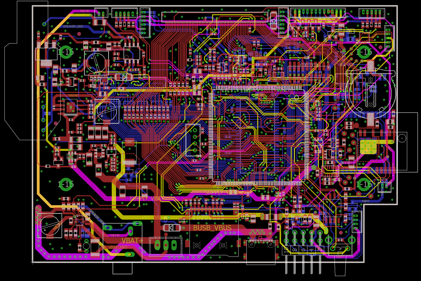
chicken feet, incl. the 6 position switch output, stopped suddenly working on my TX16S. On further inspection, I was able to identify the SiLabs C8051F330 microcontroller on the breakout board, where the 6-pos. switches and LEDs are located, to be the central part of this functionality. Right next to the microcontroller is a 3-pin C2 debug header. When connecting SiLabs 8-bit Debug Adapter to it, the chip answered, so was alive. Why, the code did not run anymore although, remains a mystery, as the chip was powered correctly, and as it turned out in a later testing, was in good condition. Anyhow, as the original flash was code protected, I was unable to read it out, in order to e.g. try to run it in debug mode to see where the problem was. Without any source, I erased the chip and started this project.

If you wonder if I contacted RadioMaster Support and asked for a source - I sure did, but what I got back is a peculiar answer: Sorry we are unable to provide that information sir, may need to consult the manufacturer of the chip. Why on earth I need to contact SiLabs for the source code of the µC in RadioMaster product... makes absolutely no sense to me.

Do note that the 6-position switch firmware does not have much to do with the OpenTX firmware (<- code that...Continue Reading
Posted by Risto | Mar 07, 2021 @ 04:04 PM | 38,166 Views
Futaba TM-10 FASST module / Futaba T10CG internal module do not communicate with the radio via std. 5 pin-header, but use an additional 4-pin header for communication. Only the power and RF-output enable feedback are sent via the 5-pin header.

Using an oscilloscope and a logic analyzer, I had a look at the signals of the 4 additional pins on the Futaba T10CG internal module (which is the same as in Futaba TM-10). First observation is, that the 4-pin header actually only carries 2 signals, as the top two pins are shorted and so are the bottom two pins. I could see that the signal carried over the two signal lines is a 3.3V level non-inverted standard serial protocol using 125000 baud with 8 data bits, 2 stop bits and even parity. The used 125000 baud 8E2 serial stream is close, but not quite matching the S.BUS signal, which would be 100000 baud, 8E2.


I attach a zipped Saleae Logic Analyzer trace that I captured for a couple of seconds before and after powering on the system. To view it, you can download the software for free from Saleae. It will work fine without the logic analyzer hardware. Be sure to zoom deep in, first then you start seeing the single bits and bytes and their corresponding decoding.

Signal correlation with an S.BUS output of the receiver

To further investigate how the communication corresponds to the S.BUS signal output by the receiver, I added a bound Futaba R6208SB receiver S.BUS output to the trace (see second attachment below). The timing of the...Continue Reading
Posted by Risto | Mar 07, 2021 @ 04:55 AM | 35,902 Views
I was not planning to use the embedded ESP32-WROOM-32 module in DragonLink V3 transmitter, so looked for a way to turn it fully off, also not to transmit anything on the 2.4 GHz band.

Unfortunately there is no official way to achieve this, also by flashing MavlinkToPassthru (Mav2PT) project is not a solution. The latter does offer over WebGUI the option to turn WiFi & BT off, but after looking at the source code, I noticed that it still does not turn off the RF-output (this is also noticeable from the fact that the WebGUI remains enabled, it just turns off MavLink output via WiFi & BT).

To overcome this issue, I created my own DL V3 ESP32 firmware (attached below for download). The code is really simple, also the procedure to compile and flash the embedded ESP32 is pretty straightforward (thanks to Noircogi for Mav2PT instructions that gave me initial ideas how DL ESP32 module is setup).

Here are the steps (without any warranty for success from me and also do not expect help from DragonLink after you continue!).

DO NOTE THAT YOU ARE WIPING THE FACTORY ESP32 FIRMWARE (but it is possible to re-flash it as instructed here). Nevertheless if you mess up something and brick your DL Tx, be prepared to take full responsibility! Also do note that the DragonLink transmitter firmware and the WiFi+BT ESP32 module firmware are two separate items. Here, we are not touching the DragonLink transmitter firmware, but only the embedded ESP32-WROOM-32 WiFi+BT module firmware.

If...Continue Reading
Posted by Risto | Mar 06, 2021 @ 08:00 AM | 35,499 Views
I created an interface to control a remote device (e.g. a drone) from the PC via a radio link and I call the project USB2PPM.

The USB2PPM circuit gets the signal from PC over USB connection and converts it to Pulse-Position-Modulation (PPM) to be input e.g. over a trainer jack into a remote control transmitter.


USB2PPM uses standard trainer port signal. Back in 2003, I did a similar project PC-to-R/C Interface V2.0, but it was much bigger than the current version and used RS-232 serial port that is deprecated today.

...Continue Reading
Posted by Risto | Mar 06, 2021 @ 07:07 AM | 36,340 Views
If you followed my blog post #5 about native MAVLink telemetry with RadioMaster TX16S, you are aware that we can use the TX16S top USB-C port in MAVLink routing mode to connect to a ground control station, such as Mission Planner or QGroundControl. To recap, I add the connection image from my blog post #5:


Without the modification to the radio hardware, as explained in this post, there is one caveat when using the top USB-C port connected to ground control station. This has to do with the specialty of the internal STM32 microcontroller, as used in most OpenTX radios, and the schematic wiring used. Namely, the main microcontroller of TX16S boots in Device Firmware Upgrade (DFU) mode when the USB cable is connected while the radio is powered-up and thus will NOT boot and run the normal OpenTX firmware. You will get a black screen when powering up in DFU mode and no functionality from the radio.

This behavior stems from otherwise a very nice feature of the STM32 microcontroller in the radio that allows it to be flashed without external programming device, even if no bootloader is yet programmed. (This is also the reason, why most OpenTX radios cannot be bricked by user doing something wrong while flashing.) Unfortunately, STM32 DFU paired with the electrical schematic in most OpenTX radios, where the BOOT0 pin hard-wired to VBUS, results in the before mentioned behavior of radio not booting in this situation. The solution is either to disconnect the USB cable from ground...Continue Reading
Posted by Risto | Mar 06, 2021 @ 06:18 AM | 36,037 Views
Update: RadioMaster offers now hollow shaft AG01s, making the mod explained in this page, unnecessary.

As a long time Futaba tray transmitter user, I was used to having additional controls on my sticks, e.g. to control a camera gimbal. After making a jump to OpenTX, got myself TX16S and made a tray modification (see my blog post #7). Nevertheless, I was still missing my old beloved stick controls.

I could not find readily available commercial solution for TX16S, so went the road of customization. Here's the final result:


The trickiest part is to get a hollow shaft into the existing sticks, as they are from solid material with a M4 thread:


I disassembled the TX16S hall sticks and very carefully in a lathe I was able to drill 2.0 mm through-holes into the stick pins:

...Continue Reading
Posted by Risto | Mar 06, 2021 @ 05:21 AM | 34,777 Views
Being previously a long time Futaba tray radio user and being accustomed to controlling sticks by pinching, I put my TX16S into a tray.

AHLtec offers two tray options for TX16S: a fiberglass and a carbon. I picked the carbon version for optics. And as I was planning to use spatially slightly separated DragonLink, instead of the internal radio MULTI-module, the vicinity to large electrically conductive carbon surfaces was less of a concern for me.


The AHLtec tray comes as a kit and needs to be assembled. It fits TX16S perfectly, the build quality of the carbon parts is excellent. I had to file a bit the mounting holes in the metal braces in order for them to perfectly fit and not damage the thread of the screws during assembly.


...Continue Reading
Posted by Risto | Feb 28, 2021 @ 07:23 AM | 36,155 Views
I modified Yaapu LUA telemetry widget to work with OlliW MAVLink enhanced OpenTX (see my blog post #5 for more info about OlliW MAVLink enhanced OpenTX).

My modified Yaapu LUA telemetry widget is available under my GitHub page (for installation instructions just follow Yaapu's original instructions here, but for the SD-card source use my GitHub fork instead).

My mod adds some new menu items to the Yaapu configuration - when using OlliW OpenTX, the MavSDK option should be enabled (in the latest version in my GitHub it is called MavSDK, here, the older screenshot says still enable MAVLink support instead):


To add waypoint data to the left panel, enable MavSDK/Mav2PT mode for it:


I added an option to update the home position using the radio attached GPS instead of having to rely on a fixed home position, where the vehicle was armed. This option can be enabled here:

...Continue Reading
Posted by Risto | Feb 28, 2021 @ 07:22 AM | 39,727 Views
I would like to introduce an option to get MAVLink telemetry directly to Yaapu telemetry screens of RadioMaster TX16S, without having to resort to Mav2PT protocol conversion anymore. This eliminates numerous problems stemming from bandwidth and payload size limitations of FrSky Passthrough protocol and is especially interesting for anyone using a radio modem with native MAVLink capability, such as DragonLink.

The main role here plays OlliW MAVLink enhanced EdgeTX/OpenTX firmware that you can load to your RadioMaster TX16S. In addition, I modified Yaapu LUA telemetry widget to work in addition to FrSky PT also with OlliW customized EdgeTX/OpenTX fork for Horus-class radios that has not only MAVLink support baked in, but also MAVLink routing baked in. For more info about my modified Yaapu LUA telemetry widget, please see my blog post #6.

I created 4 connection diagram examples for OlliW MAVLink enhanced EdgeTX/OpenTX firmware using RadioMaster TX16S, DragonLink V3, GCS and GPS as examples.

RadioMaster TX16S is an ideal choice, as it provides two easily accessible UART ports on the bottom. Nevertheless, OlliW firmware and my Yaapu widget mods should also work on other Horus-class EdgeTX/OpenTX radios, like Jumper T16, but require opening the case and direct soldering the connection cables to pads on the mainboard.

Let's start with the simplest diagram with just RadioMaster TX16S and DragonLink V3:


--------------------------------------------------------------------------...Continue Reading