Posted by Jack Crossfire |
Aug 27, 2016 @ 09:42 PM | 6,359 Views
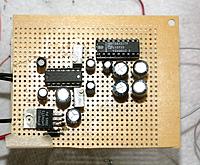
So after humming along for a few hours, the same LA4461 failed the same way it did 18 years ago. It dead shorted the speaker to the rails, overheated, & made static. Because of the commute, the decision after decades of planning to make something custom out of old MOSFETS, reading comments on the DROK, & a brief dreams of tubes, was to invest in a bog standard STA540 from $parkfun. It would also be the most compact.
The LM324 was replaced by an LF353 on a carrier board. The LM324 appeared in 1972, so judging from the sound of recordings in those days, a bipolar op-amp from those days probably wasn't up to the task.
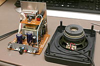
Reworking the HTR-5230 begins
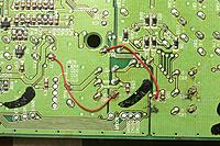
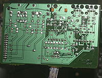
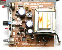
Analog input proved too noisy. Reviewing the available datasheets for the HTR-5230 revealed the TOSLINK input could be extracted from it for use in another amplifier. The dual TOSLINK inputs were multiplexed into a single input by a simple voltage level. The single input went into the 1988 era YM3436 which converted it to I2S. This was configured by simple mode select pins.
The I2S went into the 1999 era CS4227 which had the DAC. The I2S was routed through the undocumented YSS908 to process the special effects. It could easily be hotwired to bypass the YSS908.
Everything uses 5V at a fairly high current. The CS4227 is configured for SPI. You can see data on the AD1/CDIN line when changing inputs. CDOUT isn't connected. CCLK goes at 100khz & sends 2 bytes when changing inputs. CS is erratic.
The
...Continue Reading
Posted by Jack Crossfire |
Aug 21, 2016 @ 08:10 PM | 6,623 Views
Built a Baxandall tone control to try to get more treble. That did the job, but with severe distortion. The LM324 wasn't up to the job. The next step is an LF353 on a carrier board. The multiturn pots are quite impossible to center. Given the schematic for a Baxandall, simple resistor calculations give 40k when the pots are centered even though a standalone pot would give 50k. Fortunately, the only useful setting is maximum bass & maximum treble.
This is the only audio circuit the LM324 has had any problems with & the internet approves its use. Anyways, the virtual ground shows a bit of instability typical of the LM7805. Thought the distortion 10 years ago was caused by servos, but clearly it's not a perfect regulator. With the bass set to neutral, the distortion is more bearable than not having any treble. Would say the high end from the 1980's amplifier & Bax is clearer than the HTR-5230, but a true comparison with the HTR-5230 is impossible because it's dead.
Hollens family music is good at reproducing the distortion, because they have the high pitch voice & bassy piano.
Posted by Jack Crossfire |
Aug 20, 2016 @ 11:34 PM | 5,465 Views
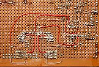
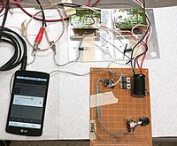
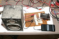
For the 1st time in 18 years, the IC pair made noise. The circuit was free from defects & did a lot better than the HTR-5230. Standby current was 160mA. They seem to need the full back panel for heat sinking. As expected, the high frequencies were gone because of the lack of a tone control. Being of much older age makes treble enhancement essential. Volume control used the ultra shmick MAX412 with 28Mhz gain bandwidth product to try to retain as much high frequency as possible.
Other than nostalgia, it's rather pointless considering a modern amplifier with 3x the power is $15. The TDA7377 does 2x30W with a lot less parts. The LA4461 does a mere 12W. Quiescent current is the same on both chips.
Posted by Jack Crossfire |
Aug 20, 2016 @ 03:57 AM | 5,729 Views
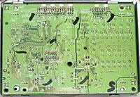
It was disappointing to discover TOSLINK was not decoded by a SOC but a very complicated, shielded board. The key component was the YSS908, an undocumented Yamaha chip which had the DAC & multiplexed all the inputs. The SDA & SCK pins revealed an I2C interface. Mike Harrison could reverse engineer it, but a better waste of time would be to use a more modern digital format than TOSLINK. The only reason for the cable was the amplifier being limited to just that. It's a miracle last year's Macbook still supported TOSLINK because of the number of legacy amplifiers.
For the moment, it's back to ages old RCA cables again. For the tone control, it would make more sense to use a digital input with EQ in a microcontroller than an op-amp. A TOSLINK decoder could be made out of a modern microcontroller, for the true believers.
Posted by Jack Crossfire |
Aug 18, 2016 @ 12:19 PM | 5,906 Views
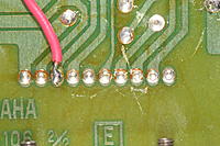
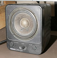
Over the years, the plan varied from reworking the Yamaha's parts into a discrete 2 channel amplifier to nihilistic plans for tubes. In the end, the future was the most economical bog standard IC amplifier. A quick test of the broken DM-01 revealed it probably failed from broken solder joints. 20 years of hindsight would have saved a lot of money, because what was succeeded by 3 amplifiers which failed in their own ways & a lot of heartache would again become the standard.
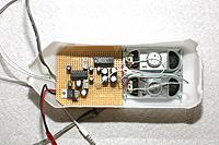
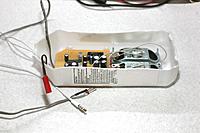
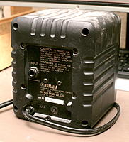
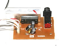
Unfortunately, the DM-01 electronics were discarded long ago & the speaker driver failed for an unknown reason. Perhaps someone put 12V directly through it. Whoever discarded the electronics strangely left behind the heart of the DM-01: manely the LA4461. The LA4461 is a long discontinued single channel IC with a lot more external components than a modern part, but the nastiest bits of the LA4461 were all preserved on its carrier board. Datasheets 30 years ago were a lot harder to read.
The mane piece not on the carrier board was an oscillation suppression circuit. The test seemed to work fine without the oscillation suppression circuit. The LA4461 produced plenty of loudness from the phone with no additional gain. The only other piece in the discarded section was the tone control. This seemed to be a standard op-amp circuit which combined volume with bass boost. It could be reverse engineered, but the mane requirement in old age is treble boost. The rest was all power supply.
...Continue Reading
Posted by Jack Crossfire |
Aug 17, 2016 @ 12:40 PM | 5,420 Views
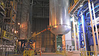
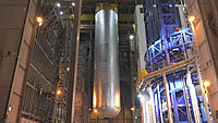
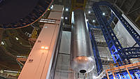
Behind the nonstop H-Rod worshiping, this was built. Liquid methane would have been 1/3 the size. The 1st, cheapest configuration would be 8.3 million lbs of thrust or slightly more than a Saturn V. The SRB's alone would nearly match a Saturn V. This increase would lift 154,324 lbs to LEO or 1/2 the Saturn V capacity. All the increase in thrust to lift less to orbit is government at it's best. The SLS uses 2 stages instead of 3. The 2nd stage has a lot less power because it uses a 1950's pre-Apollo engine to save money. Recycling shuttle components came with a lot of compromise.
The LH & LOX tanks are the 1st things in 50 years purpose built for a manned lunar mission. The tanks are 35% larger than the tanks on the shuttle.
Posted by Jack Crossfire |
Aug 15, 2016 @ 10:24 PM | 5,435 Views
The 1st drive with the speakers was manely successful, owing to experience finally forseeing requirements. The weight was manageable. Low frequencies were quite good. They were just loud enough to overcome traffic & deafening in quiet areas. Either the battery faded or the TDA1517 overheated, because they were a lot more clipped near the end.
Posted by Jack Crossfire |
Aug 14, 2016 @ 05:56 PM | 5,253 Views
Because every launch has a few tweeks, it's tempting to collect as much trajectory information as possible in 1 table. Kiwipedia has hardly any trajectory information. JCSAT-16 was a GTO instead of a supersynchronous orbit like last time. The separation velocity was a hair lower to allow the single engine landing. Perhaps this means they found more money can be made by more consistent landings than by giving the customer more speed.
Orbcommmm LEO SUCCESS: 2m25s 6012km/h 74km
1st return to land
JASON-3 POLAR FAIL: 6147km/h 66.5km
Failed landing leg
SES-9 supersynchronous FAIL: 8325km/h 64.6km
CRS-8 LEO SUCCESS: 2m34s 6608km/h 71km
barge landing
JCSAT-14 supersynchronous SUCCESS: 2m41s 8355km/h 66.6km
Payload separated at 36276km/h 207km
1st 3 engine landing
THAICOM 8 supersynchronous SUCCESS: 2m40s 8343km/h 65.6km
3 engine landing, bent struts
Eutelsat/ABS supersynchronous FAIL: 2m39s 8361km/h 65.7km
3 engine landing with longer single engine phase. ran out of fuel
CRS-9 LEO SUCCESS: 2m22s 5688km/h 59.6km
1nd return to land
JCSAT-16 GTO SUCCESS: 2m36s 8156km/h 64km
Payload separated at 35240km/h 208km
single engine landing
Doing the math during today's 8.9 miler, it became clear that the BFR will be 13.5million lbs of thrust or 1.8 more powerful than the Saturn V. If thrust was proportional to the LEO mass, it would translate to 500,000 lbs to LEO. Full reuse is converging on 1/4 of the expendable payload, giving 140,000 lbs to LEO. It's probably enough for a capsule full of 100 people. There would have to be another flight full of fuel & supplies. A permanently orbiting booster would take the MCT to Mars. Fortunately, someone is working on the problem.
Posted by Jack Crossfire |
Aug 13, 2016 @ 11:11 PM | 5,373 Views
So Dr. Franklyn got some long needed grinding to add more clearance. It had no problems other than rubber hitting plastic where the manufacturing was off by a few mm. Other than that, Dr. Franklyn has a bit of plastic filings around every moving part.
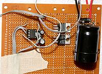
Finished the poor lion's speaker, finally. Due to some kind of accident, it only has 950uF for the mane power when the datasheet said 2000uF. That might explain why it didn't do the full waveform for 4R speakers, but it also might require 14V to support 4R speakers.
So 2 speakers paired to give 8R to a single channel is what it is for the 1st test.
Posted by Jack Crossfire |
Aug 13, 2016 @ 01:04 AM | 5,346 Views
The answer is yes. Automated cams work. They're not completely foolproof, but with enough error protection can do a decent job. The 1st automated cam ended up being LIDAR based. The trick with LIDAR was building dense point clouds out of many passes.
All the basic limitations of XV-11 LIDAR apply. It only detects horizontal motion, not vertical. It only works indoors. It can't handle lots of mirrors & windows. It can't detect anything more than 4m away. It can't handle 2 simultaneous sources of motion. It does better at night than daytime with sunlight coming in. The worst case is the camera pans away from the subject.
The less ideal conditions can be handled by classifying more pixels as outliers, but this makes the camera lag more. The room had a small number of windows which still resulted in a usable amount of lag. It tracked for 45 minutes at night without any failures. As the subject moves farther away, the harder it is to get the camera to track with the amount of filtering required for the windows. It's very limiting to not have vertical tracking.
There's still a plan to try a machine vision approach, with its own set of limitations. A thermal cam might do it, but these are extremely expensive.
When the mobile app billionaires finally get automated cams fast enough & reliable enough for the masses, they're going to be a game changer just like brushless gimbals. GPS quad copters won't do it. Cheaper LIDAR is the key.
Posted by Jack Crossfire |
Aug 07, 2016 @ 09:10 PM | 7,271 Views
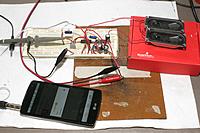
Soldered it in a stereo configuration with a pair of 4R speakers. This went down like a lead weight. Despite the LM324 providing both sides of the waveform thanks to its actively driven virtual ground of 5V, the TDA1517 only put out the bottom half. The TDA1517 didn't even turn on at the vehicle's 8.4V. The input protection diode dropped it to 7.7V & this was below the minimum. It needed 9V to turn on, which the diode dropped to 8.3V.
For some reason, wiring the speakers in series to give 8R got both sides of the waveform. This only amplified a single channel, but seemed to be loud enough to do the job. The circuit needed 0.25A, so a tiny 350mAh cell would boost the vehicle's voltage enough for it to work. The mane problem is enclosing it all in a module suitable for attaching to the vehicle.
It's theorized that the speakers can use the cargo bay as a resonator instead of requiring their own box.
Posted by Jack Crossfire |
Aug 06, 2016 @ 01:40 AM | 5,186 Views
If only lions knew 20 years ago what they know now. Of course, there was no way to look up how to connect a TDA1517. Sadly, lions have no interest in building audio amplifiers anymore. If the interest of the 25 year old lion was combined with the knowledge of today, it would have saved a lot of money & grief.
It was an experiment to get more sound reinforcement for less weight, but speaker drivers have to be heavy to be loud. The TDA1517 can get plenty of loudness from large, heavy speakers but the same job can be done by a $10 bluetooth speaker.
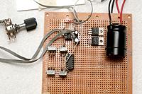
An LM324 inverting amplifier with virtual ground can boost the phone output to the 1V peak to peak that the TDA1517 does best with. Key to the preamp is actively driving the virtual ground with a voltage regulator. If the virtual ground is passive or a follower output, the LM324 will only generate the negative side of the waveform.
Posted by Jack Crossfire |
Aug 04, 2016 @ 04:30 PM | 5,636 Views
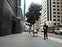
There's no obvious sign of a 16" sink. There are cracks not unlike all the other streets. The windows are a bit closer to the ground than the neighbors, but they're not visually misaligned from the neighbors. The only smoking gun is a wall outlet right next to street level. Either the entire street has sunk or there have been a lot of repairs to keep it looking normal.
Posted by Jack Crossfire |
Aug 03, 2016 @ 10:28 PM | 5,540 Views
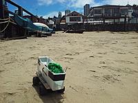
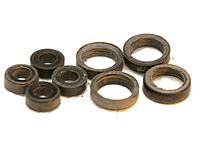
The metal bearings arrived after 7 days, got installed, & the steering was suddenly rock solid. Months of dicking with PID constants were suddenly proven meaningless. The internet wasn't kidding about plastic bearings being no good. Steering wobble is the mane symptom of worn bearings. The metal bearings should last forever, but the plastic axles also wore down a bit. There's always going to be some wobble.
Went up to 10mph with a shirt payload & didn't get any wobbling. This should get much better video. The new bearings & new differential are much noisier than before. The next step would be a metal differential, so the noise is a fact of durability.
Posted by Jack Crossfire |
Aug 03, 2016 @ 12:51 AM | 5,740 Views
So basically, detecting motion via difference keying was a total failure. The noise from the webcam in indoor conditions was too close to the noise from the motion. Furthermore, indoor light sources always overwhelmed any other objects. It couldn't tell whether a subject or the camera was moving because color changes by indoor points of light overwhelmed any global color changes.
The next, super simple idea, was to use the old XV-11 lidar module to detect motion.
The XV-11 tries to detect a lion walking around the room. A window reflects the LIDAR in 1 place, but doesn't affect its ability to detect motion. The soundings are shown in polar coordinates, then in X-Y coordinates. It does 4.9 revolutions per second. 4 revolutions are stacked to try to reduce the noise, but it doesn't look good for LIDAR motion detection. The lion goes 3m away. Another project is sharing the tripod with the LIDAR.
The problem was once again noise. It would have a hard time differentiating the bubbling of the stationary wall 3.5m away from a slowly moving subject. Of course, there's still a chance common differentiation between the LIDAR plots will prove more robust than feared, but that's another commute away.
The X-Y or the polar plots could be differentiated. The X-Y plot would detect motion tangential to the camera better than motion towards the camera. The polar plot would probably do better in both axes.
Since the camera is stationary, another method is taking a long LIDAR exposure & just subtracting it like a static scene. It would have a hard time with furniture & pillows changing position.
Posted by Jack Crossfire |
Jul 31, 2016 @ 10:15 PM | 5,266 Views
So with the Feiyu busted, there's nothing to do than try some other project. The latest idea with the Feiyu was to replace the MOSFETs with some other motor controller which didn't have the reluctance problem. Perhaps it would mean running 9 extra wires outside the gimbal, making it so cumbersome as to defeat the purpose of using a Feiyu in the 1st place. Ideally, there would be replacement MOSFETs with lower deadband, but the same form factor. The means by which the Chinese overcame the reluctance is another great mystery which you just have to forget about in the name of having something work.
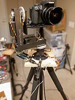
It was finally time to go ahead with the motion tracking camera. The motion tracking camera could always have been a very compact Gopro deal, using standard servos. The supply of standard servos is now considered consumable, as the lunchbox destroys them all. The X-Y platform had been around for 3 years with something like this in its future. It was decided to go for the maximum dynamic range of the DSLR.
A webcam would provide the machine vision to the computer, since capturing the DSLR's analog video would take more space. The entire X-Y platform is lighter than the Giotto head, so it was decided to mock it up in place of the tripod head. Designing the mockup & attaching it to the tripod took 2 days.
The mane problem is any motion tracking algorithm depends on a camera that moves to track the motion. It can't detect motion when the camera is moving. There are some ideas for solving this.
 Views: 183
  Views: 176
  Views: 192
  Views: 186
  Views: 192
  Views: 187
  Views: 181
  Views: 192