Posted by Jack Crossfire |
Sep 30, 2012 @ 01:03 AM | 7,517 Views
So the networking came together. All beacons from the laptop to any wireless address have go to the copter, because that's how it just is. Linux can't put in anything except the copter MAC as the destination for every IP address.
Then the copter has to shuffle the addresses in the 802.11 header & forward some packets to the camera. The camera beacons contain servo X & Y. The camera sends picture data in response, to the copter. The copter forwards it again, to the laptop.
The address shuffling is:
Code:
                  dst address, src address, filter address
---------------------------------------------
laptop to copter: copter, laptop, camera
copter to camera: camera, copter, laptop
camera to copter: copter, camera, laptop
copter to laptop: laptop, copter, camera
Miraculously, it works but loses a lot of packets.
There are probably ways to manually override the MAC address on all the wireless cards or get them into promiscuous mode, so anyone can talk directly to anyone. It would require more investment in the driver, sending packets out of order, or using the laptop networking stack in a way which won't work everywhere. Eventually, the copter is supposed to process everything.
This scheme ended up not working very well. Either there are a lot of collisions or the USB bandwidth on the copter isn't high enough to do all the packet forwarding.
The return packets from the camera may conflict with the return packets from the copter. The forwarded beacons double the bandwidth usage, reducing the maximum beacon frequency.
There's no consumer product which has 2 wireless stations communicating in realtime with a single tablet. If it's sending video, it's 1 access point & 1 tablet. If it's a sensor network, it communicates very infrequently.
This is heading back towards a tethered USB device, with hope the tablet has a USB host adaptor.
Posted by Jack Crossfire |
Sep 29, 2012 @ 01:28 AM | 7,163 Views
So the easiest way to have the ground camera & aircraft on a wireless network was to make the aircraft an access point & hard code the ground camera as associated. The aircraft has the lowest latency link to the tablet & the ground camera doesn't need full duplex, which doesn't work.
All the data from the ground camera needs to go through the aircraft. The address manipulation required to do the packet forwarding is unknown & complicated.
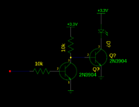
A little BJT magic got the LED flashing without a tether. The IR receiver has a timeout which is just slightly longer than the duration the LED has to be on. If the framerate is any lower, it needs to toggle the LED in software.
The dual camera vision system made the 1st 3D test measurements & it was extremely high performing. 20Hz still looked fluid fast. Deriving the center of the blobs from the dimensions of the blobs & moving the servos gives the distance measurement more resolution than 640 pixels.
Thresholding the greyscale on the microprocessor has been successful at getting a high framerate mask. A software change could make it use a bicolor LED. Greyscale does 640x240. A bicolor LED would do 320x240 because there are only 320 color columns from the sensor.
Posted by Jack Crossfire |
Sep 27, 2012 @ 07:14 PM | 7,797 Views
The latest discovery was converting a servo to 360 usually fries the electronics. Because you want linear motion to be faster than angular motion, you give the motor 12V, which goes into the power rails through the spudger diodes & fries the electronics. Even 5V could fry the electronics from back EMF. The only safe way is a fixed resistor for the pot & PWM control, very slow. There's also cutting the motor traces.
There have been many times when custom servo firmware would be a win. A super servo would run on 12V, have a way to control the motor speed through PWM, time out if the pot doesn't move, increase the update rate to thousands of Hz, increase the precision by averaging more pot values, power down the motor, step the motor using a tachometer or timer. There are probably many such things, using bulky Arduino boards.
Such a servo would have allowed great things, during last year's laser painting, especially averaging pot readings to increase precision. Completely overhauling the microcontroller must not have been in the budget.
The alt/az mount for last year's laser painting was built in winter 2011, for a dead 2.4Ghz camera on a failed ground rover. In summer 2011, it was recycled into a stationary alt/az mount for a webcam that would unsuccessfuly fly Marcy 1 outside. That was converted again to a laser pointer in Oct 2011. Then, the electronics were simplified & it was restored to the web cam which successfully flew Marcy 1 in Jan 2012. It
...Continue Reading
Posted by Jack Crossfire |
Sep 27, 2012 @ 12:55 AM | 7,086 Views
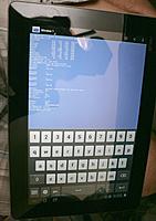
Everything from the cameras to the copter had to be wifi because it had to be controlled from a tablet. For any consumer UAV to be viable, it has to support tablets. The tablet arrived.
Somewhat dreaded its arrival. Not totally convinced about tablets, despite their ubiquity in retail. M.M. was a die hard Apple fan, but Android is the long term destiny of everything. It is the current best Android tablet available, much lighter than a pad, has a micro SD card. The screen is still much lower resolution than the 'pad.
Also not crazy about it because it's not a development platform. It's ground up meant for people who only care about the brushed aluminum & glossy plastic. The user interface is too cluttered with eye candy & invisible in daylight because there's no way to make it black & white.
Wifi can't connect to Marcy 2, it can't play any videos from Cinelerra, but it does have a command line. It constantly sends DHCP requests & sets its address without ever finishing, but the command line doesn't have any network tools. Eventually it stops sending DHCP requests & says the access point is saved, without being connected.
Posted by Jack Crossfire |
Sep 26, 2012 @ 01:10 AM | 7,287 Views
A pan/tilt mount has become the least common denominator for indoor position sensing, whatever the vision algorithm is. Kinekt realized it. Webcams have had pan/tilt mounts forever. It's no longer prohibitively expensive.
Distance sensing worked well enough to go ahead with the pan/tilt mount. It turned out horizontal drift was from pausing the camera clock. If the camera clock was paused by turning off the GPIO, it drifted. If it was paused by turning off the timer, it stopped drifting. Turning off the GPIO added 1 more pulse than turning off the timer, but unless the camera has a 2nd clock, it shouldn't matter.
The frame rate made it up to 40fps, giving 20Hz position updates. The hope is wiggling the servos will increase the horizontal resolution beyond 640. Higher resolution cameras would be nice.
Every pan/tilt mount has to be sent out to make money, so a lot of time goes into building new ones.
Posted by Jack Crossfire |
Sep 25, 2012 @ 01:41 AM | 7,411 Views
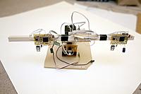
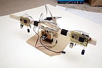
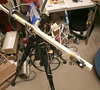
The cameras finally went on the wooden rod, to try to align them for distance sensing instead of video. The resolution had to be increased to 640x240 & the framerate reduced to 30fps to get any useful distance. Still another problem emerged where 1 camera slowly glitches its horizontal position.
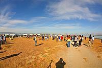
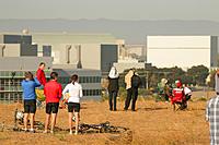
The CF card also had some shots of the shuttle viewing mob. They always vote against the space program, but turn out en masse for a view of some hardware.
Posted by Jack Crossfire |
Sep 24, 2012 @ 12:10 AM | 7,295 Views
It's an electronic abomination, but stereo vision works. 5Mhz through a ribbon cable, heavy dependance on realtime network performance, hackneyed SPI protocol, pausing the camera clock for synchronization were cost saving measures better done without.
So the clock trimming register was not accurate enough to synchronize the cameras, but it turned out there was a blanking interval at 1/2 the frame height, where the camera clock could be paused without affecting exposure. The slight pause reduced the framerate to 67fps but nailed the synchronization.
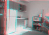
Put together some 3D video to show what it can do.
It takes extremely precise alignment for 3D to work. Lens spacing has to be optimum for the distances. The lenses have to be angled towards the neutral depth plane. Those consumer cameras with fixed lenses are worthless & no-one is going to spend the time tweeking all the required parameters.
During this process, noticed the TCM8230 still generates ITU 601 luminance & Goo Tube still expands ITU 601 luminance. Most every other modern camera generates 0-255 luminance, so all your still photos & phone videos are getting clipped on Goo Tube.
The camera system remains wireless, hence the glitching.
In video mode, it maxes out at 18fps 320x240. In object tracking mode, it does 67fps 320x240. Using it for making videos is an utter waste of time, compared to buying 2 Chinese HD cams.
It wasn't the 1st 3D experiment on the blog.
https://www.rcgroups.com/forums/showthread.php?t=743863 3D experiments usually last a few posts before the motion sickness ends them.
Surprising to find Jim Cameraman was the 1st to use a beam splitter mirror to make a 3D camera system. That allowed greater flexibility in the intraocular distance & convergence than was possible before. Now, every professional 3D camera system uses a beam splitter.
Posted by Jack Crossfire |
Sep 22, 2012 @ 07:22 PM | 7,327 Views
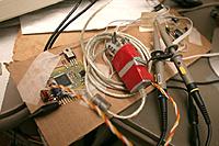
After another round of bridged traces, the stereo cameras finally returned video. The target output is only a single LED at 70fps instead of greyscale at 5fps, but greyscale is useful for testing.
Those last bridged traces were fiendish, with pressure on the board & flux remover causing some shorts above the resistance threshold of the continuity tester. The SPI cam has an excessively high error rate. It's independent of clockspeed or cable losses. What a rough design, compared to an FPGA.
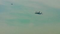
In other news, got some shuttle footage.
Didn't know if the bridge would be fogged in, so shot video of it flying over M.M.'s former territory. The bridge ended up being the premier location & this ended up being almost the worst location. We had an F-15 escort, while LA had some F-18's.
Posted by Jack Crossfire |
Sep 21, 2012 @ 12:02 AM | 7,386 Views
So a posterized image with white blacks is a sign of a bridged trace. Probe the data pins for strange voltages. That bridge also made the clock die above 40Mhz & I2C die. Now images from either camera come through at 70fps, the clocks go at 56Mhz, the SPI communication properly accesses the left camera at 1.6Mhz, but using both cameras simultaneously makes it crash.
Surprising just how fast the board layout kills high frequencies. The SPI ribbon cable dies above 2Mhz. The purely etched clock trace only carries 1/2 the voltage at 56Mhz.
Posted by Jack Crossfire |
Sep 19, 2012 @ 11:28 PM | 7,169 Views
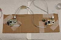
Dual cameras with dual microcontrollers has been every bit as hard as expected. It would definitely be better done with an FPGA, but the microcontrollers were on hand.
They comprise a modular component used 3 times & the FPGA would have taken some time to bring up. The FPGA would still give much better results if the system proved successful.
The SPI drops bytes from the start of the buffer & has a strange alignment requirement. The cameras are proving flaky to get started on the new board.
Debugging along the chip communication path, step by step, SPI is proving difficult to switch between transmit & receive. You need 1k resistors to keep dueling outputs from burning out, but that causes quite a degradation in signal power.
The mane surprise was that #define has proven superior to bridging pins.
Tweeking the HSI calibration value in response to frame period is all that's needed to synchronize the cameras. They automatically line up just by changing the period, but the synchronization is pretty bad. The HSI calibration value isn't as precise as hoped. It also destroys the UART output.
Posted by Jack Crossfire |
Sep 17, 2012 @ 04:07 AM | 7,599 Views
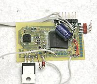
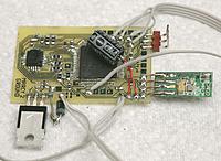
The 1st big test of the Hendal was the fabrication of the 2 boards for Marcy 2's stereo vision. The only problems with the Hendal continued to be the short cable length, bulky box, & clumsy iron holder.
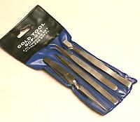
Together with an el cheapo $5 tweezer set, these boards came together faster than anything before. The tools of decent board fabrication & soldering have definitely gotten cheap enough for anyone to build anything except BGAs.
The mane problem is once again communication between the 2 CPUs. SPI using DMA has a few quirks. Cables have to be protected against competing outputs. $parkfun seems to be phasing out the TCM8230 in favor of slower but easier UART cameras.
Posted by Jack Crossfire |
Sep 14, 2012 @ 02:26 AM | 7,194 Views
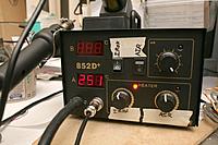
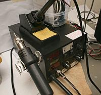
It's rebranded as many 1 hung low brand surface mount rework stations. After 1 day, it seems to be pretty good. It's quite a step up from the 20 year old Weller. It's definitely a business only case, unlike the blue/yellow/pink cases of most gear.
It heats very fast & quickly recovers from loss of heat, allowing it to do a lot more at a lower temperature. The Weller needed 340C to do anything, because it couldn't recover from a loss of heat. The Hendel only needs 250C on the iron & heat gun. The tip is much finer than the weller, but wicked long. It could destroy your eyes or any nearby LCD panel.
The heat gun actually works, using 250C, the smallest tip, & full airflow. It pulled off a 100 TQFP without any issue. Airflow is quite significant. You wouldn't think a long, narrow tube could move that much air. The temperature accuracy is nowhere. It always put out 200C, whether set 100C or 150C.
The mane problem is the box is huge & the cables are too short to have it anywhere besides right next to the project. The heat gun has the flimsiest tube with no stress relief. It's another tool which can't be permanently in the same place.
Posted by Jack Crossfire |
Sep 07, 2012 @ 04:34 AM | 6,862 Views
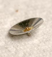
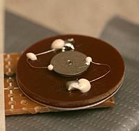
A note that the sonar transducers can be taken apart, but while disassembling them makes them look omnidirectional, they actually produce no sound.
Posted by Jack Crossfire |
Sep 02, 2012 @ 01:31 AM | 7,622 Views
An idea came to run the cameras at 640x240. Only horizontal resolution is required for depth. Vertical resolution can be lower by an unknown amount, still limited by altitude accuracy. Extremely fast, accurate altitude is required.
Besides that, attention turns to SPI & dual camera synchronization, not the high bandwidth world of video processing. SPI has to change directions & use DMA. That takes a lot of playing with finished hardware, since there's no multimaster SPI DMA example.
There were some ideas to have a timer on the right ARM drive the clock of the left ARM. There's resetting a timer on the left ARM at the start of every left frame. The timer value at the start of every right frame shows if it's ahead or behind.
There can be a delay state, where the camera clock is paused for a few loops. There aren't any easy ways to speed it up.
It might be possible to slightly slow down both to 65fps by adding a 1ms delay to the master. They could both pause their clocks after a frame. The master would trigger the slave to resume after 1ms. It could be an acceptable reduction in frame rate. That would reduce the position update rate from 35 to 32Hz. It's unknown what the minimum rate for stable flight really is. Overexposure from the delay is a real problem. It could overexpose the whole frame or just 1 random pixel.
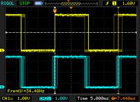
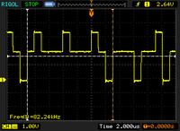
Officially, the Rigol says the maximum is 68fps. The synchronized framerate would be 64fps.
There is a HSITRIM register which trims the ARM clock. The algorithm would be 1st measure the time between right eye frames. If it's too long, increase the clockspeed by 1. If it's too short, decrease the clockspeed by 1.
If it's in the bottom half of the left eye frame, increase the clockspeed by 1 if no change or revert if the change was -1. If it's in the top half of the left eye frame, decrease the clockspeed by 1 if no change or revert if the change was +1.
Posted by Jack Crossfire |
Aug 31, 2012 @ 07:24 PM | 7,499 Views
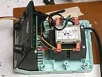
After many years & many attempts to keep it going, the Weller finally died. Its heating element seems to have burned out like a lightbulb after 15 years. It started years ago as intermittent failure to heat, which could be defeated by pressing the cable in. Eventually, pressing on the cable stopped working.
A new heating element would be $133, while a Hakko is $80. It still has a working 5:1 50W transformer, potentiometer, & switch. It could be an easy power supply for something else or a source of magnet wire.
In other news, the great task with vision is repurposing the same circuit board for both ground cameras & the aircraft. The same circuit board is used in all 3, with minor firmware changes. There are ways to do it in runtime, by grounding some pins or bridging some pins. There are ways to do it at compile time.
Compile time is a lot more labor intensive, requiring 3 different images to be flashed, 3 different objects being compiled from the same source, either simultaneously or based on a makefile argument. Historically, multiple objects from the same sources have been a lot more challenging than bridging pins.
The PIC autopilots had different enough boards & source code for the ground, aircraft, & human interface that different source code wasn't a burden. Those autopilots would probably move to identical boards & firmware, too, with the same pin shorting to determine firmware behavior.
 Views: 334
  Views: 263
  Views: 286
  Views: 247


