Jack Crossfire's blog View Details
Archive for June, 2009
Posted by Jack Crossfire | Jun 30, 2009 @ 04:25 AM | 10,490 Views
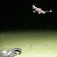
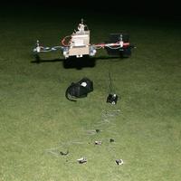
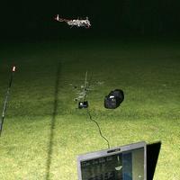
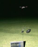
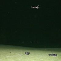
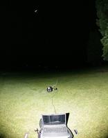
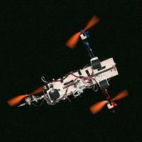
Autonomous camcopter takes flight (0 min 37 sec)


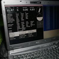
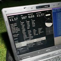
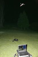
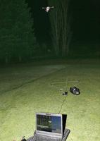
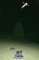
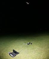
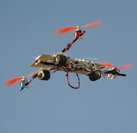
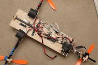
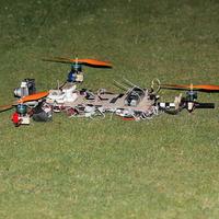
There it is. The first video from Vika 1 with the tiny boards & DT700 motors. Finally got the automatic takeoff, turn, shoot, & land mission to work, but since it was dark, U get only 1 angle. Drew the battery all the way down to 9.3V. Who knows where the Super Simple ESC's shut off.

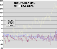
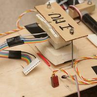
Magnetometer was useless because of the payload balancing requirement, but the ADXRS gyros pulled off a solid flight in 3DOF IMU mode.

Vika 1 in rate gyro mode with the SCP1000 is still the Jesus copter. The tiny board interferes less with GPS. Her magnetometer needs another calibration. Newer magnetometers advertise automatic degaussing, but the Micromag3 is free.


After spending 3 hours waiting for web pages to load, VicaCopter 4 is finally available for download. If U ever succeeded in downloading the source code & building your own VicaCopter, U still probably wouldn't know half of what she can do.

It's amazing after all these years, VicaCopter is still the only English language source code for a fully functional helicopter autopilot that you can download without paying for.

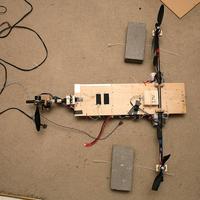
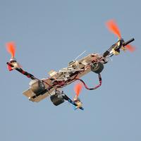
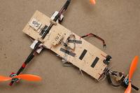
Still undecided about going for a micro tri rotor or another spin copter. Vika 2 has some more sonar algorithms ahead. An EDF based spin copter might work if the EDF can survive crash landings. All roads lead to moving the LCROSS budget up to July.
Posted by Jack Crossfire | Jun 29, 2009 @ 12:54 PM | 9,839 Views
https://www.rcgroups.com/forums/showthread.php?t=823496

Previous work on heading hold algorithms showed the commercial gyros U see on runryder.com making snap turns probably don't use closed loops, but until yesterday, no-one knew if it was true or just our super low feedback rate.

When the pilot moves the stick, it bypasses the heading hold part & passes the stick directly to the servo. When the pilot releases the stick, the feedback loop regains control & locks whatever the new heading is.

There's no way a heading hold gyro based on totally closed loops would give the connected sensation an RC pilot wants. So what happens if U use a heading hold gyro for cyclic? The constant cyclic inputs all bypass the heading hold part, making it useless. For manual flight, a heading hold gyro for yaw would work, but in autopilot the yaw has constant inputs too.

Now U could convert the target orientation to microcontroller units & have the microcontroller track attitude in its own frame of reference directly. None of this could be easily converted to an embedded computer & the goal with ground based autopilot was easy porting back to embedded computers.

No, if U want 200Hz feedback, there's no way around a realtime embedded computer. Yet another myth busted.
Posted by Jack Crossfire | Jun 28, 2009 @ 08:22 PM | 10,044 Views
Heading hold mode takes flight (1 min 22 sec)


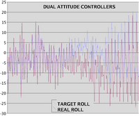
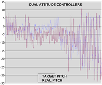
So this was heading hold mode on the airframe & full quaternion feedback on the ground in 105F weather. The ground computer commands cyclic at 50Hz to achieve a target attitude & the airborne computer commands cyclic again at 200Hz to achieve the desired change in attitude.

Unfortunately, there was too much lag between position feedback & attitude. The heading hold software isn't tuned for the optimum response. Any time U command changes in attitude instead of absolute attitude, you're heading for serious lag, but heading hold gyros can do snap turns so U still have a few more blog posts 2 go.

Vika 1 heading hold implementation (1 min 43 sec)
...Continue Reading
Posted by Jack Crossfire | Jun 27, 2009 @ 05:29 PM | 9,943 Views
Like a lost tribe worshipping a 40 year old plane wreck in the jungle,

http://news.sky.com/skynews/Home/Wor...ewspaper_Warns

every anti-US day, North Koreans gather around a rusted US spy ship they seized 41 years ago & chant some kind of hate speech. It makes U wonder what they worship on Ford Pinto day.

The answer is yes. N. Korea can get a nuke to Calif* & kill a lot of U. It doesn't need 2 B accurate. A missile hitting the remotest part of Calif* would wipe out a billion people. At least there R plenty of low paid flat broke programmers & unemployed missile defense workers they can hire.

The answer is no. They can't shower nukes on U. Long range missiles R going 2 B a once annual event because they don't have enough money to build any more. N. Korea's best move would be selling missiles to someone else, but Kim Ill the IIIrd doesn't want to be a mere peon for the Iatolla.
Posted by Jack Crossfire | Jun 26, 2009 @ 12:24 PM | 9,849 Views
So you're going to get heading hold on all the gyros with the 200Hz feedback, another round of test stand runs, probably another week before anything flies again. Now some notes.

EQUILIBRIUM TILT IN A 3DOF IMU

Equilibrium tilt seems to work in a 3DOF IMU.

To make Vika 1 turn on a dime, she has a fixed neutral tilt hard coded for the body frame & changes a second, variable tilt in the world frame to respond to position. No matter where she's pointing, the variable world frame tilt is converted to body frame & added to the constant neutral body frame tilt to get the target attitude.

The variable tilt in world frame is contained in the integrals of the PID equations. Because we add the neutral body frame tilt after position feedback, the integral limits for position feedback don't need to encapsulate the neutral body frame tilt.

What happens in a 3DOF IMU where the current body frame tilt is constantly reset to 0? This IMU assumes whatever it senses is always the neutral body frame tilt after a reset. Instead of resetting to 0, you reset to the hard coded neutral body frame tilt.
Posted by Jack Crossfire | Jun 25, 2009 @ 12:26 PM | 10,033 Views
Originally VikaCopter had a small integral on the airframe to give her some heading stability. When rate feedback went to 200Hz, that went away.

Face it, ground based autopilot is no match for the copters with 200Hz onboard feedback. U only thought 50Hz was enough because rotomotion.com used 25Hz. Given the need to fly in smaller spaces, maybe it's time to put orientation feedback back on the airframe.

The cheapest method is to stick with ground based autopilot & implement heading hold for all the gyros. While U debate that, how about another photo run.
Posted by Jack Crossfire | Jun 24, 2009 @ 03:46 AM | 10,054 Views
U know, we don't have a clue what causes most sonar clocking anomalies. They're affected by the value of SONAR_HISTORY.

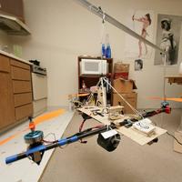
So in our efforts to shrink the useful flying space to dumpy apartment size, we have a 1ft array. Sonar can certainly detect the copter below 2m but can't keep her in an apartment sized box. Takeoffs R still out of control. Suspect the large airframe has too much inertia & a micro copter might do a better job.

Tried some circuits & it was pretty bad. Without a full 9DOF AHRS & with that confined space, U can't match Vika 1.


So how did microdrones.com get those super tight videos of the nerdy guy pushing the copter? He's got a super expensive RTK GPS system, the airframe is smaller than Vika 2, it's got a full 9DOF AHRS, it's super balanced to not require as much lowpass filtering, & of course super fast feedback on the airframe....Continue Reading
Posted by Jack Crossfire | Jun 23, 2009 @ 12:48 PM | 10,347 Views
As you've probably gathered, an autonomous copter doesn't give U much more pilot bandwidth than a manual copter. If 1 person had to fly one of the commercial UAV's with the super complicated ground stations, how much information would they really get from the ground station? Normally, U have a spotter outside shivering while someone else stares at the screen in a van.

Extremely stable weather in the last 48 hours gave U some extremely good sonar performance. Got some attempts at equilibrium tilt with the 3DOF IMU. It's questionable at best. No other issues with the IMU. Pushed the sonar range again.

You've got a 2x2 meter box at 4m of altitude where sonar is most reliable.

Running PICOC in a fork paid off. Had crashes from the return; keyword not being implemented but the copter didn't...Continue Reading
Posted by Jack Crossfire | Jun 22, 2009 @ 01:32 PM | 9,682 Views
So the oscillations were the sonar clock drift & nothing sinister with 3DOF IMU's. The LISY300AL is indeed more stable than the IDG300. It's not an ADXRS613, mind U.

2 days of hard sonar debugging & she's triple bingo again with the tiny board. Working around clock jitter by checking the ground station & rebooting if it's out of limits, just like we do with the battery, gyros, radios, landing gear, servo, ESC's, propellers, & rubber bands.

PICOC isn't reliable enough to run in a thread. Got PICOC running in a fork instead of a thread & flying a few successful missions from takeoff to landing. Equilibrium tilt for 3DOF IMU's would be nice. U also need takeoff & landing ground station status.

Horizontal range seems to be +/-2m at 8m of altitude. Vertical range is 6-12m. Not sure it would be any better indoors with a micro copter.

Got 8 minutes out of the 4Ah & 7m30s out of the oldest 3.3Ah, so there's a minor improvement from the tiny boards.

HOME MADE ESC NOTES

The schematic for a home made ESC is here.

http://mikrokopter.de/ucwiki/en/BL-Ctrl_V1_1

Home made ESC's would be nice. Doubt we can get them any smaller than the Castle 9. Combining the ESC's & computer on 1 board may pay off with the indoor copter.

They would allow collecting RPM & current data, which no ESC can do. RPM knowledge would eliminate the hacks for different batteries.

Designing an ESC seems to be pretty simple. Power 1 of 3 circuits at a time with a P & N mosfet. Wait for open circuit voltage on the next circuit to rise above the average voltage. Switch to the next circuit. Shut down if current exceeds a limit.
Posted by Jack Crossfire | Jun 22, 2009 @ 12:37 AM | 9,719 Views
The average RCGroups blog poster lasts 2 years. Most of the content in the Blogs is the same. Human activity doesn't vary much. With less money in circulation & more in treasury notes, there's much less happening in the world.

The internet is a lot slower than it was in 2006. 1 minute page loads R now considered fast on Sunday evening & business hours.

HOW TO DESIGN A SPACE SHUTTLE TRAJECTORY

Make the space shuttle fly as low & slow as possible to get a given payload into orbit with the maximum fuel load. For lighter payloads, fly shallower. For heavier payloads, fly steeper. Base maximum payload on the steepest trajectory U can safely abort from, not the amount of fuel.

U want to make it as easy as possible to abort & always drain the tank completely regardless of the payload. Even hauling a feather should drain the tank completely. Any extra fuel means U risked the astronaut's lives needlessly.

JAVA IS BACK


Have some pretty serious clocking errors with the tiny boards. Another hand tuning of crystal frequencies for that one, but the jitter problem continues. It may require a hardware solution if USB isn't realtime enough. It takes a lot of tweeking to tune each sonar system.
Posted by Jack Crossfire | Jun 19, 2009 @ 11:31 PM | 9,386 Views
https://www.rcgroups.com/forums/showthread.php?t=838443

Java was slow. Keystrokes lagged. U couldn't remember the keypresses to navigate the menus. It took a lot of power to render the GUI. The artificial horizon was pretty bad in flight. It took too long to decipher information on it. That had everyone looking at a text interface.

Most people cram a bunch of traditional airplane instruments in a window. How well does that work on a phone? How would U send PICOC commands to the vehicle?


Most important factoids:

BATTERY VOLTAGE
gps satellites/sonar SPL
thrust balance
2.4Ghz bitrate
72Mhz bitrate


Not exactly what Goog spits out, but personal experience. Easy to get on a command line, but we want extra optional factoids like gyro bias. Graph format data would be nice. Maybe an EKG machine, because what you're doing is monitoring health & not flying anything. When we're out working, it's easier to navigate with a keyboard than a touch pad.

Wish list:
Easily readable fonts.
White on black for daylight.
Make voltage, GPS satellites, & thrust balance big enough to see from far away.
Graph & numeric options for each factoid.
Automatically partition based on enabled graphs.
Bingo board for IMU state.
Posted by Jack Crossfire | Jun 19, 2009 @ 12:04 PM | 9,169 Views
Payload & engine performance is mostly constant. Sensors capable of detecting the first few feet of altitude R heavy, expensive, & unreliable. It takes a lot of fuel & time to hunt for equilibrium thrust. An adaptive takeoff algorithm gets U on North Korean headlines, but all roads lead to hard coding.

Rocket launches R hard coded. Put the SSME at 104% & go. John Carmack was the first to use a carefully tuned PID controller & burn a lot of fuel to take off. For some reason, rocket hobbyists all copied him.

Maybe we've gotten jaded about physics. Went from a totally adaptive vision to over 200 parameters in configuration files. Some of it is configuring your own GPS system.

BIAS BUSTERS

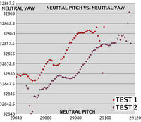
Now for the first time ever, it's a graph of neutral pitch vs. neutral yaw on the same IMU. They're coming out consistent on the same day, but not days apart. Suspect there R mechanical instabilities in the gyros which keep any temperature table from getting the last bit of gyro bias. Since we're using another gyro as the thermometer, it squares the error from mechanical instability.

Yaw bias from pitch bias is busted yet again, but hopefully we still can get yaw bias from position, the most cooly deadly looking a piece of calculation as ever U have laid eyes on.

BUDGET BUSTERS

Sonar is killing the budget. It requires flying low & fast over a sea of electronics & quickly damaging something after only a few minutes every commute....Continue Reading
Posted by Jack Crossfire | Jun 18, 2009 @ 12:52 PM | 9,304 Views
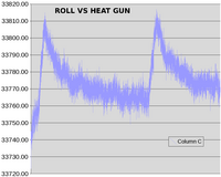
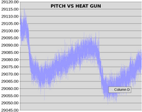
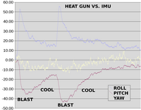
Using pitch & roll drift to estimate the yaw drift is a myth you've been busting for years. It didn't work with the IDG300, but that was a much bigger package.

Let's blast the IMU with the heat gun & see what happens. If the temperature changes slowly enough to keep them all matched, U can probably derive yaw drift from tilt drift. In flight, they emit different amounts of heat, they're blasted by prop wash & their heat capacities differ.

If U get tired of reading about 3DOF IMU's, U can give up & install an AK8976A from www.asahi-kasei.co.jp. That's a 3 axis magnetometer & 3 axis accelerometer on 1 chip.

Unfortunately, those single chip 6DOF deals R exclusively for phone companies like Apple. You're stuck with an HMC5843 for $20 & an ADXL320 for $8. That would double the IMU tag.

AUTOMATIC TAKEOFF & LANDING NOTES

For Vika 2 automatic takeoff & landing, U don't have a position signal until a minimum altitude is reached & U can't tell when the minimum altitude is reached without a position signal. Ramp collective & fix attitude, hoping the sonar field catches it above a certain level before it flies away. Get the starting position when minimum sonar amplitude is reached & engage position hold.
Posted by Jack Crossfire | Jun 17, 2009 @ 12:29 PM | 9,540 Views
2 days on the Blog page. Either U people R too focused on your day jobs or The Goog changed its algorithm.

Ghetto blimp

Another idea is ghetto blimp. Instead of those gigantic envelopes U multi billion dollar home owers stuff away in your 1,000 sq ft mansions, ghetto blimp would be an 11" party balloon. It would offset some of the weight of the computer, sonar, & Xbee. The electronics + $20 Walmart power system would hang under it & it would spin around like spin copter. It would use the same throttle phasing & unbalanced payload to get translation, but solve the weight problem with heleman.

It would be completely impractical, but it would prove indoor sonar flight & eliminate the risk of spin copter.

The minimal sonar autopilot is coming in at 10g. The balloon reduces it to 5g. U could probably get the autopilot to 5g by using a 900Mhz radio chip, no sonar amplifier, & eliminating the Walmart computer.

Unfortunately, any time U introduce blimps, it turns into a toy.

Atmel vs Microchip 900Mhz

AT86RF212:
fully powered antenna output
smaller package


MRF49XA:
needs RF choked antenna power
bigger package
not at digikey

Everything from Atmel is newer. We would interface the chips with SPI & forget about extra microcontrollers. Probably couldn't fit GPS in Vika 2's RAM with that method.

More Vika 2 4 U


Whew. Vika 2 is definitely a crash prone wreck. The Super Cheap ESC's don't cut off. She's too...Continue Reading
Posted by Jack Crossfire | Jun 16, 2009 @ 03:24 AM | 9,964 Views
So there's no way to get the full power out of Super Cheap ESC's if there's any noise in the PWM at all. 1 glitch over the maximum pushes the automatic throttle calibration lower & causes U to have not enough power. To get maximum power out of the Super Cheap, U need PWM with no noise or ESC's that allow fixed throttle range.

Worked around noise on Vika 1 by having extra PWM table entries, but took the entries out for spin copter, then ported spin copter back to Vika 2 & it didn't work. U need the extra table entries.

> West winds 10 to 20 mph...becoming 5 to 10 mph after midnight.

Your government still labors under the delusion that cold fronts bring lighter winds. Sonar guidance got another attempt in the wind anyway.

4 today's movie, John Carmack had another hit with Human vs. Rocket. Man with balls of steel pulls Methane/LOX rocket.

Human vs. Rocket (2 min 38 sec)

Posted by Jack Crossfire | Jun 14, 2009 @ 05:33 AM | 8,325 Views
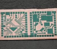
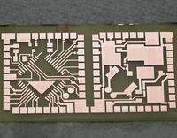
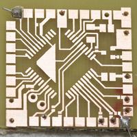
Now that you're $90 bankrupt on etching, there's no need to use XBees anymore. The XBee is the weight limiting part for spin copter. U can get bare XBee chips for $3. No UART, only SPI. Indeed, you'd need your own radio for any commercially viable UAV.

For 900Mhz you'd now skip the XBeePRO 900 & build your own out of an MRF49XA & a bag of parts. 7dBm output power compared to 17dBm for the XBee. With the $200 still blown on 2.4Ghz video, upgrading at least 1 copter to 900Mhz radios is a good idea.

Weight comparison:
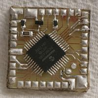
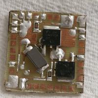
Bare through hole Vika 1: 3.8oz
Surface mount Vika 1 with dongles: 1oz

Mind U, extra voltage regulators R required for lighting & GPS on the SMT board.

Wish list:
2 scratch built 900Mhz modules
Switchable 900Mhz ground station mode
$20 spin copter test
Mirror lens
Posted by Jack Crossfire | Jun 13, 2009 @ 03:49 AM | 8,363 Views
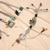
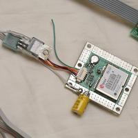
Whew. That was murder. No way this would ever be economically viable. You're definitely better off from a weight, size, & cost standpoint to have every sensor on the board. Our $parkfun breakout board collection doesn't leave many options in that regard. Built 3 autopilots with those & they're always a mess.

Someone still had to discover it was a mess & that's what the Jack Crossfire blog is 4.
Posted by Jack Crossfire | Jun 11, 2009 @ 12:33 PM | 8,425 Views
Going over the Walmart specials again, a spin copter would take buying lots of toy copters & finding out if any have enough power. There's no other way. $100 was the price of finding out 12mm brushless motors R too heavy to land.

The Havoc Cyclone looks like it might work if chopped up. Lift junk hardware first. Etch a single sided board with no voltage regulator. Single sided is lighter than double sided. That's July's budget.

Our double sided boards cost 2x as much & weigh 2x as much because they need 2x the etching board & the vias R too big. Their only advantage is the form factor & the wow factor for our Iranian readers.

SSME nugget 4 U

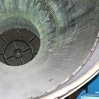
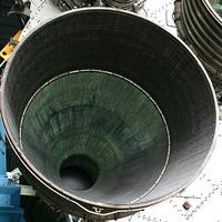
The answer is yes, the SSME has 1000 tiny tubes on the inside of the nozzle, not the hatbands U see on all the media photos. The outside rings R called hatbands & just keep it from falling apart. Didn't know this, so didn't get a high resolution photo of the tubes. Only got a wide angle photo of the nozzle.

The tubes R 1/4" in diameter on the aft end & shrink to pin size as they approach the forward end. Liquid hydrogen flows from the aft end to the forward end to keep the nozzle from melting. The tubes R braze welded to the nozzle wall. Finding leaks is real hard.