Jack Crossfire's blog View Details
Archive for April, 2017
Posted by Jack Crossfire | Apr 29, 2017 @ 02:17 AM | 6,839 Views
The Gopro made another trip to the city, yielding another haul of side firing remote cam videos. The mane interest was capturing the mane in an epic mile before it was cut off. The side firing cam definitely gives better results than the rear firing cam.

Lion hits a 6m55s mile (7 min 42 sec)


Lion cools down (3 min 41 sec)
...Continue Reading
Posted by Jack Crossfire | Apr 29, 2017 @ 02:12 AM | 7,055 Views
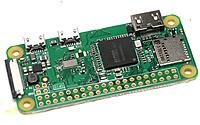
After 12 desperate years, we finally have a cheap, miniature way to bridge a USB host to Wifi & bluetooth. All those gadgets which only provide a USB device controller for I/O can now be wireless.
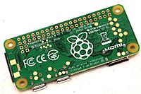
Unlike the previous pi's, it really can function in the given form factor instead of requiring a bag full of peripherals. They finally fixed the problem of having to desolder 40 pins to access the GPIO header or having to desolder a bunch of headers to gain access to the USB & power signals. Wires can be soldered directly to large test pads on the back.


The heart of the beast is the BCM4343X, now sold as the CYW4343X. It's a bare die & a sign of how all chips are going to be packaged in the future. It provides all the wireless functions. The same chip is used on the raspberry PI 3B.


The bluetooth side of the BCM4343X is accessed by a UART. The kernel uses hciattach to attach the UART to the networking stack. Then, bluetoothd converts the socket interface into a d-bus interface. The python examples use the d-bus interface.


Current consumption is <300mA at 5V. Clockspeed is 700Mhz to 1Ghz. The kernel can be cross compiled, but all other C programs have to be compiled on the pi to satisfy dependencies. The mane program which needs to be compiled is bluetoothd. This takes 30 minutes & an 8GB flash card.


You must install the full raspian distribution, not the lite version to do anything useful. The 1st partition is a vfat boot partition. The 2nd...Continue Reading
Posted by Jack Crossfire | Apr 16, 2017 @ 05:16 PM | 6,532 Views
Minitaur Explores the Outdoors (2 min 58 sec)


Ghost Robotics had another video, shortly after the last blog post. It's pretty slow on uneven terrain. Legged robots are once again busted.

Meanwhile, the lunchbox had a pretty successful 19 mile drive. It used 3455mAh from battery 1 on the bottom. 4374 from battery 2 on the top. It carried 12oz of fluid for 12 miles & the speaker for 19 miles. With the speaker & a drink, it was the mobile party originally envisioned. It reignited the idea for a new wheeled vehicle with a low center of gravity & much higher payload.

Electric skateboards now abound, but still can't steer remotely & they still cost over $600. They still work, despite rigid axles & no shock absorbers. With the Inboard M1, they started putting the motors inside the rear wheels instead of coupling by exterior belts. The hub motors still provide enough thrust to move a human around & take the minimum space. They might use a planetary gear but the millenial reviewers are completely unconscious about how anything works.

The skateboard is the model for the smallest possible drive train. Steering still requires a big servo outside the wheels. With no shock absorbers or tilt steering, the payload could be right down against the wheels.
Posted by Jack Crossfire | Apr 14, 2017 @ 11:57 PM | 7,439 Views
The closest you'll get to a vintage computer might be the FT2232. It's 1 of the older FTDI chips, but apparently still in production, widely available, & quite capable. It's a dual serial interface. The high end is the FT4xxx line which are quad serial interfaces.

The trick with the FT2232 is to not use the commercial drivers, but use libftdi. Most of the commercial drivers don't support it but libftdi does. Also, libmpsse provides limited abstraction of libftdi into SPI, I2C, & GPIO interfaces, but it doesn't allow simultaneous GPIO control & hardware protocols which the FT2232 does allow & it has many bugs. The trick is to refer to libmpsse to get the command structure for the hardware protocols, but directly call libftdi commands in your own program to control the GPIOs.

It's not clear how he figured out the command structure besides sniffing packets as they went through libusb. FTDI doesn't document it anywhere. Fortunately, it's not a very complicated protocol. The chip doesn't have any concept of GPIO, SPI, I2C modes the way libmpsse does. Libmpsse just uses mode settings to determine what commands to send, but the chip can accept any command in any mode.

The hardest part is figuring out the pins labeled GPIOH & GPIOL are ambiguous. What's really happening is all the pins labeled ADBUS are GPIOs written in a traditional 8 bit GPIO register & all the pins labeled ACBUS are written in another 8 bit register. They can be...Continue Reading
Posted by Jack Crossfire | Apr 07, 2017 @ 12:15 AM | 7,251 Views
It was a long & hard process between 1 month of commutes, but Heroineclock I was finally shut down after 13 years of blinking & replaced by a much better Heroineclock II, factoring in much more experience.

Introducing Heroineclock II (4 min 0 sec)


All the Chinese options which appeared in the last 13 years were studied & found to be too expensive. The largest Chinese digits were 12" tall & $50. EL wire would cost a fortune. Projectors were too dim & small. Superbright red LEDs had dropped from 22c to 15c & become much brighter.

With the new experience, power consumption dropped from over 20W for Heroineclock I to 7W, yet light output increased greatly. The audio synthesizer was much more sophisticated, with 3 square wave oscillators & decay timing. The clockspeed was increased from 20Mhz to 40Mhz to allow the improved audio. The new speaker driver was a real PWM driven class D with the 0 crossing at 50% duty cycle. The speaker brought the total current with all the LEDs & sound to 0.6A.


The flaky buttons & switches which plagued Heroineclock I were replaced with an IR remote. It was a 1st experience decoding an IR remote & it revealed IR receivers don't output RS232 but PWM. The decoding had to be really schmick for it to handle the rapid button presses involved in setting a clock.


The shift registers which drove Heroineclock I's LEDs were replaced by direct wiring to 1 GPIO per segment....Continue Reading
Posted by Jack Crossfire | Apr 03, 2017 @ 01:20 PM | 11,215 Views
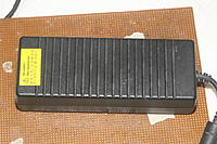
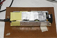
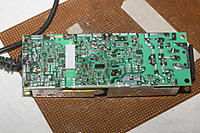
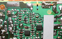
The answer is yes, you can change the voltage of a laptop power supply, within limits. It was long dreamed of changing a 12 year old, 20.5V, 6A deal into a more useful voltage. 1st was discovering that it could be opened. 2nd was discovering there was a common circuit in most power supplies. It could be probed for by providing DC to the output instead of connecting the manes voltage. With the output powered, look for 2 inputs of an op-amp. 1 input should be around 2.5V, the other input should be a ratio of the output voltage.

The ratio is determined by a resistor divider. In this case, it was an irrational number around 15 for the high side & a complicated network for the low side. Decreasing the high side would raise the op-amp input & lower the output voltage.


Whacked in a parallel 47k which reduced the output to 16V, but what the internet didn't say was on a scope, it was a sawtooth. With load, it was 8-16V. Without load, it was 14-16V. Whacked in a 100k & 1 meg in parallel to finally yield a voltage of 17.9, right on the edge of where it became unstable but .1V low enough to power the Accucel 8150. Another 1 meg in parallel threw it off.


The problem is it needs a minimum voltage to power itself. It tries to bootstrap itself when it turns on, but if the minimum voltage isn't reached, it indefinitely tries to bootstrap itself. That's what generates the sawtooth waveform.

The 2.5V reference is generated by a Xena diode labeled 1273. It's...Continue Reading