Posted by Ribble |
Mar 17, 2015 @ 10:48 AM | 38,990 Views
2.4 gHz magic number 31.25 mm
1/4 wave antenna is 31.25 mm long, sometimes less.
The speed of light is slower in a medium than in free space.
Radio waves travel slower when in coaxial cable or when encased in a dielectric tube. A quarter wave is shorter unless it is plain wire. It is the time it takes a radio wave to travel a quarter wavelength in a medium that determines the actual length.
In coaxial cable, a quarter wavelength is typically only 65% to 70% of the length in free space. Called Propagation Factor.
http://en.wikipedia.org/wiki/Velocity_factor
A quarter wave antenna works because, the tip of the antenna is almost infinite impedance (high voltage and no current) and 1/4 wave closer to the receiver it is very low impedance (low voltage and high current), where the impedance matches the 52 ohm impedance of the coaxial cable. This does not work for a one half or full wavelength, but does work for 1/4 or 3/4 wave antenna. A dipole is two 1/4 wave wires fed with opposite polarities (one connected to coaxial cable center wire and other connected to coaxial cable shield).
A 1/4 wave antenna is good. A dipole is 3db better. A 3/4 wave needs a time delay or phasing stub which makes it a 5/8 wave antenna and harder to get correct but does have higher gain than a 1/4 wave antenna or dipole antenna.
---
Ez-12 Parabolic Reflector Template
http://www.freeantennas.com/projects/template2/
LiPo battery care
Cold slows chemical reactions. Heat...Continue Reading

Comments (19)
Add Comment
Posted by Ribble |
Jan 09, 2015 @ 09:28 PM | 8,519 Views
Mode 2 (left stick Throttle and Rudder) Calibration
Start with with CX-10 and transmitter power off.
Put CX-10 on a level surface and power on (rear red LEDs on solid and front blue LEDs blinking fast)
Transmitter power on (beep) (beep) (front blue LEDs blinking slow) Now binded
Throttle full on (beep)
Throttle full off (beep) (All LEDs on solid) Motors now "Armed" to run
>Throttle stick push in twice (beep beep) (beep beep beep) Newest version with black motor bottoms
Throttle stick down and left same time elevator stick forward and left (front two blue LEDs blink slow)
Release sticks (front two blue LEDs on solid) CX-10 now calibrated
"The crazy back motion only occurs when trimming a lot."
To be exact:
12 trim tabs down elevator - full down elevator and add throttle
or
12 trim tabs left aileron - full left aileron and add throttle
CX-10 Notes
https://www.rcgroups.com/forums/show...&postcount=750
AAA cells - 1.5v - Lithium and Alkaline
http://lghttp.18356.nexcesscdn.net/8..._specs/l92.pdf
AAA NiNH 1.2v cells work fine.
Transmitter and CX-10 Pairing
Cheerson changed the transmitter protocol during production so old CX-10's are different than new CX-10's, and old and new do not pair. Apparently old protocol used red printed circuit boards on CX-10 and transmitter.
Could be people were shipped transmitters and CX-10s packed with a mixture of old and new. Yes, that should not happen, but Cheerson should not have changed protocols in mid stream either without adding a version number change so everyone can tell which is which.
Confusion will persist until there are no more CX-10's and only CX-10A headless mode (like it or not). It seems to be that the transmitters for CX-10 and CX-10A are the same with the headless function implemented in the CX-10A itself.
Discussion, photos, CX-10 USB plug and 100mah battery protection circuit board, schematic
https://www.rcgroups.com/forums/show...0#post30653275

Posted by Ribble |
Sep 10, 2012 @ 03:11 PM | 8,440 Views
SCREWS
First Flights
Diode Voltage Drop - To lower voltage of a supply source
SCREWS
Changing to new version swashplates and carbon main shafts should have added some screws. On the ones with Delrin main gears, you can grab extra screws from the ring collars as the thicker Delrin main gears should allow the main shaft to drop without disengaging the pinion.
Then you have gobs of extra screw that can be robbed from the dual-charger and transmitter.
Reminds me, when putting screws back into plastic, turn the screw backwards (out) until you hear a click as the screw finds the original threads, then turn the screw in. Avoids stripping the plastic threads.
---
First Flights
If you have problems getting into the air, try getting the helicopter quickly to eye level to get out of the ground effect, or hand launch if all else fails. You may find a slow lift-off causes the helicopter to scoot left, so be prepared for it. A slow lift-off can be done smoothly after you learn to control the helicopter.
A good launch pad is a (soft) cardboard box about 2 feet high. Then fly forward off the edge into clean air. The helicopter will drop but you already are adding throttle so just keep adding more.
All my V911's will violently scoot left (viewed from tail) on take off. I think it is the tail rotor pushing it left. When in the air, there is a right tilt on hover which means the left drift is being corrected by right aileron. That is the way they hover, even after setup...Continue Reading
First Flights
Diode Voltage Drop - To lower voltage of a supply source
SCREWS
Changing to new version swashplates and carbon main shafts should have added some screws. On the ones with Delrin main gears, you can grab extra screws from the ring collars as the thicker Delrin main gears should allow the main shaft to drop without disengaging the pinion.
Then you have gobs of extra screw that can be robbed from the dual-charger and transmitter.
Reminds me, when putting screws back into plastic, turn the screw backwards (out) until you hear a click as the screw finds the original threads, then turn the screw in. Avoids stripping the plastic threads.
---
First Flights
If you have problems getting into the air, try getting the helicopter quickly to eye level to get out of the ground effect, or hand launch if all else fails. You may find a slow lift-off causes the helicopter to scoot left, so be prepared for it. A slow lift-off can be done smoothly after you learn to control the helicopter.
A good launch pad is a (soft) cardboard box about 2 feet high. Then fly forward off the edge into clean air. The helicopter will drop but you already are adding throttle so just keep adding more.
All my V911's will violently scoot left (viewed from tail) on take off. I think it is the tail rotor pushing it left. When in the air, there is a right tilt on hover which means the left drift is being corrected by right aileron. That is the way they hover, even after setup...Continue Reading
Posted by Ribble |
Sep 06, 2012 @ 10:19 PM | 8,515 Views
V911 Wind-Surfing
Many flyers wind-surf with V911's because you can try anything with a V911, not fearing a damaging crash - worst case, $20 V911 BNF, just buy another one and use the old one for parts. If you are afraid to crash, then don't wind-surf.
Start by not using ailerons. Rudder is much quicker.
Apply full forward trim to keep the nose from coming up too high, and fly low, to avoid letting the wind get it.
Practice hovering nose into the wind . Push the nose down and apply throttle to hold position or to move forward.
To gain forward speed when nothing else works, turn to the side and fly a crosswind zigzag pattern.
Practice nose-left (counter-clockwise) circles to fly around and nose dive into the wind again. Ease up on the nose and bank one way or the other into the oncoming wind. Nose-right circles may be faster but harder to control (recover) after you get downwind.
Lots of practice. In calm or little wind, practice nose-left circles: Nose down to get forward motion, then full left aileron followed by small amount of left rudder, then aileron neutral, gets smooth banked wide circles. Use rudder to control diameter and throttle to maintain altitude, or allow the helicopter to dive close to the ground under the wind.
Forgot to mention that you always keep moving, crosswind zigzag, or circling back. Zigzag picks up speed when you turn. Circling back picks up speed downwind after turning into the wind and diving into the wind head-on. The fun part is at...Continue Reading
Sticky:
V911 Notes 01
Posted by Ribble |
Aug 16, 2012 @ 02:02 AM | 11,664 Views
V911 Binding
Newer Version V911 Transmitter
Origami 2k-2k-1k Transmitter Rudder Modification - Reduces Rudder Throw
Vibrations
Gradual Rotation
Binding Yellow V911 Helicopter
V911 Stock Batteries
USB Hub Charging Batteries
Transmitters That Bind And Fly V911 Helicopter
V911 Wind-Surfing
V911 Binding
Transmitter off, throttle minimum
Helicopter on
Transmitter on quickly while V911 LED is blinking fast
You may have to turn the transmitter OFF and ON after V911 LED blinks slow again
V911 LED is on solid after good binding.
Newer Version V911 Transmitter
The original V911 transmitters moved the rudder so much that the helicopter was hard to control. The newer version reduced how much the rudder stick causes the helicopter to rotate and makes flying the V911 much easier. In low rates, the newer version transmitter shows two tabs on the LCD display for full left or full right rudder.
https://www.rcgroups.com/forums/show...ostcount=11780
Night flying and reduced current draw. Numerous measurements
https://www.rcgroups.com/forums/show...s#post22546678
V911 TX Mods
https://www.rcgroups.com/forums/show...a#post22546678
Battery = 7.61v = 6x NiMh LSD 1.2v 2200mah AA cells
76.1ma = Normal LCD off
92.5ma = Normal LCD on
100ma = Normal Beeping
33.1ma = Current into 3.3v voltage regulator Vin = 5.13v ... RF Input power ~ 3.311v x 33.1ma = 110mw (about 20dbm)
13.1ma = 5 Red LEDs Vf = 1.817v
Origami 2k-2k-1k Transmitter Rudder Modification - Reduces...Continue Reading
Newer Version V911 Transmitter
Origami 2k-2k-1k Transmitter Rudder Modification - Reduces Rudder Throw
Vibrations
Gradual Rotation
Binding Yellow V911 Helicopter
V911 Stock Batteries
USB Hub Charging Batteries
Transmitters That Bind And Fly V911 Helicopter
V911 Wind-Surfing
V911 Binding
Transmitter off, throttle minimum
Helicopter on
Transmitter on quickly while V911 LED is blinking fast
You may have to turn the transmitter OFF and ON after V911 LED blinks slow again
V911 LED is on solid after good binding.
Newer Version V911 Transmitter
The original V911 transmitters moved the rudder so much that the helicopter was hard to control. The newer version reduced how much the rudder stick causes the helicopter to rotate and makes flying the V911 much easier. In low rates, the newer version transmitter shows two tabs on the LCD display for full left or full right rudder.
https://www.rcgroups.com/forums/show...ostcount=11780
Night flying and reduced current draw. Numerous measurements
https://www.rcgroups.com/forums/show...s#post22546678
V911 TX Mods
https://www.rcgroups.com/forums/show...a#post22546678
Battery = 7.61v = 6x NiMh LSD 1.2v 2200mah AA cells
76.1ma = Normal LCD off
92.5ma = Normal LCD on
100ma = Normal Beeping
33.1ma = Current into 3.3v voltage regulator Vin = 5.13v ... RF Input power ~ 3.311v x 33.1ma = 110mw (about 20dbm)
13.1ma = 5 Red LEDs Vf = 1.817v
Origami 2k-2k-1k Transmitter Rudder Modification - Reduces...Continue Reading
Posted by Ribble |
Aug 16, 2012 @ 12:57 AM | 11,313 Views
Transmitters That Bind And Fly V911 Helicopter
V911 Wind-Surfing
Motor Overheating
Gyro Test
Spins nose-right (clockwise) problem
Rudder Fake-out
Mixing Arms Reversed
Troubleshooting And Other Information
Stuck Servo
Servo Repairs
V911 Helicopter Printed Circuit Board (PCB)
Transmitters That Bind And Fly V911 Helicopter
Stock V911 transmitter (and V929 quad transmitter), still best bang for bucks.
Turnigy 9x and clones
FS-CT6B - What I use when wind is steady, allows hands off hover pointing into wind.
DH9116
Unconfirmed report that Trex 100 is "fully compatible"
FS-T6 reportedly
In my opinion, the best for price, performance, ease of use, is the stock V911 transmitter. But then I only fly V911's in low rates windsurfing outside, Elevator trim full forward.
V911 Wind-Surfing
For forward flight with the V911, push the nose down and add throttle. Throttle makes it go faster as well as maintaining altitude.
When playing in the wind, keep the nose down or the V911 will float away in the wind. Control forward speed with throttle. Practice nose-left (counter-clockwise) turns to circle around and dive back into the wind. Nose-right turns are easy but hard to pull out of because the V911 picks up too much speed.
Motor Overheating
To check for motors overheating, touch the main motor and kiss the tail motor. Touching tail motor to your nose also works quite well, but my nose isn't calibrated for heat. After you kiss the tail motor, get in the habit of blowing air into...Continue Reading
V911 Wind-Surfing
Motor Overheating
Gyro Test
Spins nose-right (clockwise) problem
Rudder Fake-out
Mixing Arms Reversed
Troubleshooting And Other Information
Stuck Servo
Servo Repairs
V911 Helicopter Printed Circuit Board (PCB)
Transmitters That Bind And Fly V911 Helicopter
Stock V911 transmitter (and V929 quad transmitter), still best bang for bucks.
Turnigy 9x and clones
FS-CT6B - What I use when wind is steady, allows hands off hover pointing into wind.
DH9116
Unconfirmed report that Trex 100 is "fully compatible"
FS-T6 reportedly
In my opinion, the best for price, performance, ease of use, is the stock V911 transmitter. But then I only fly V911's in low rates windsurfing outside, Elevator trim full forward.
V911 Wind-Surfing
For forward flight with the V911, push the nose down and add throttle. Throttle makes it go faster as well as maintaining altitude.
When playing in the wind, keep the nose down or the V911 will float away in the wind. Control forward speed with throttle. Practice nose-left (counter-clockwise) turns to circle around and dive back into the wind. Nose-right turns are easy but hard to pull out of because the V911 picks up too much speed.
Motor Overheating
To check for motors overheating, touch the main motor and kiss the tail motor. Touching tail motor to your nose also works quite well, but my nose isn't calibrated for heat. After you kiss the tail motor, get in the habit of blowing air into...Continue Reading
Posted by Ribble |
Aug 07, 2012 @ 12:20 PM | 10,290 Views
Solder bridge the Motor Overload Protection System (MOPS). Suggest scraping some green enamel and splash solder across, right below the two MOPS leads (white line between leads). This grounds the source leads on the two motor FETs (like on the DH9104) Do not remove the MOPS orange loop.
You can put a wire jumper across the MOPS connections, but you stand a chance of ruining those connections, which are critical. So create a solder bridge below the connections. The solder bridge will have some resistance and there will remain some minor motor protection. To later undo the solder bridge, move the soldering iron down the gap between the enameled copper.
.

9116-PCB-Bottom 9116-PCB-Bottom
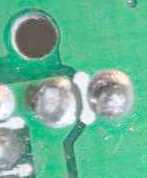
MOPS leads - Scrape green enamel below and solder bridge
.
rexless
>I've put on a solder bridge and that solved the problem. I can now spool up to full power without any cut-out affect.
>It was recommended only to do this with the stock battery - my plan is to use a 900mah 20C (40C burst) battery.
Adding more battery mah with a battery that weighs the same as the stock battery does not add any additional workload. A higher "C" rating allows you to fly harder, though the average workload will still be about the same - unless you use the additional available power to fly straight up for a long time, or stall a motor by not turning throttle off upon crashing..
Adding more battery mah with a battery that weighs the same as the stock battery does allow flying longer with added...Continue Reading
You can put a wire jumper across the MOPS connections, but you stand a chance of ruining those connections, which are critical. So create a solder bridge below the connections. The solder bridge will have some resistance and there will remain some minor motor protection. To later undo the solder bridge, move the soldering iron down the gap between the enameled copper.
.
9116-PCB-Bottom 9116-PCB-Bottom
MOPS leads - Scrape green enamel below and solder bridge
.
rexless
>I've put on a solder bridge and that solved the problem. I can now spool up to full power without any cut-out affect.
>It was recommended only to do this with the stock battery - my plan is to use a 900mah 20C (40C burst) battery.
Adding more battery mah with a battery that weighs the same as the stock battery does not add any additional workload. A higher "C" rating allows you to fly harder, though the average workload will still be about the same - unless you use the additional available power to fly straight up for a long time, or stall a motor by not turning throttle off upon crashing..
Adding more battery mah with a battery that weighs the same as the stock battery does allow flying longer with added...Continue Reading
Posted by Ribble |
Aug 07, 2012 @ 12:16 PM | 9,220 Views
The servos run off the +5v voltage regulator. You can short circuit the voltage regulator and it will just limit the current and work fine when the fault is cleared. Shorting the voltage regulator would drop the gate voltage on the motor switching FETs and turn them off, stopping the motors.
The servos have +5 volts on the center pin (of three) and you can plug the servo connector in backwards with no damage, the servo just won't work. Someone a while back was using a jumper wire to short the servo connector and all it did was reset the DH9116 receiver.
Sounds unlikely that a bad servo could cause damage to anything else.
What will kill the circuit board is stalling a motor. Kill the throttle before you crash. Stalled motors will suck up all the amperes that the LiPo or Li-Ion battery can provide and with a good battery, something has to burn out. It can happen faster than the Motor Overload Protection System (MOPS) can act.
DH9116 printed circuit boards are quite rugged and take much abuse.
Posted by Ribble |
Aug 07, 2012 @ 12:11 PM | 8,906 Views
MOSFET
Yes, MOSFET - Metal Oxide Semiconductor Field Effect Transistor.
In the beginner section, one should not abbreviate. Spelling out what MOSFET stands for only makes it worse.
In the case of the DH9116, they are power transistors that are controlled by an electrical charge on the "gate". Put zero volts (ground) on the gate and the transistor turns off (turns very off, like it isn't there). Put +5 volts on the gate and the transistor turns on (turns very on, like a direct short). The gate only needs a voltage and no current, so the power needed to control the MOSFET is practically zero watts.
Fantastic devices. The two MOSFETs on the DH9116 printed circuit board can switch (I seem to recall) 80 amperes to turn the main and tail motors on and off.
A short circuit dissipates no power. An open circuit dissipates no power. The MOSFETs only dissipate power during switching, the transition between a short and an open.
But voltage spikes from the motor's inductance during switching will kill a MOSFET. So, across the main and tail motor connectors are "snub" diodes to short motor spikes.
Enough electronics. MOSFETs are such a mystery to RC helicopter pilots, but are as vital as the LiPo batteries.
Posted by Ribble |
May 13, 2012 @ 09:47 PM | 9,591 Views
Toy 2-LED Dragonfly for V911 night flying.
SIZE: The propeller part is the same diameter as the V911 blade diameter. The blade hub slides firmly down over the V911 flybar.
LEDs: Easily disassembled by gently pulling the plastic pieces apart. The electronics are two LEDs, one on each side, a core of three AG1 Button Cell Batteries (alkaline 13mah), and a very strong eyelet screw that turns into the batteries connecting one set of LED leads to the battery. Eyelet screw switch works very well to turn LEDs on and off, so precise it can even be set to switch on vibrations.
The LEDs are parallel with the battery and are actually blinding at arms length. They are the floodlight kind, 4 inch circle at 1 foot distance, another 8 inch circle at 10 feet, 3.14 volts across the LEDs, eyelet is (-). No resistor. Non-blink blue LEDs on the one I pulled apart. Two LEDs lit, no heat.
Each LED (+) end will slide out of the plastic leaving the other LED still functional. Each LED (-) end unwraps from the eyelet with a half twist.
NOW THE GOOD PART.
The LEDs must have internal resistors because they work fine across a V911 stock battery. No heat, just blinding light. And no damage if you connect backwards.
So, for $0.38 each, you get two floodlight LEDs with internal resistors and a 3 cell battery. Tape a few of these units to the v911 for night flying and when the battery is dead, wire the LEDs to the LiPo 3.7 volt battery.
Have not timed them, likely will last at least...Continue Reading
Posted by Ribble |
May 13, 2012 @ 09:27 PM | 13,936 Views
FS-CT6B Transmitter with V911 Helicopter
https://www.rcgroups.com/forums/show...postcount=6240
The FS-CT6B transmitter is a cheap way (about $35) to try something other than the V911 stock transmitter.
One place has pre-order for $27 (Stock: -1017) buy Mode 1 or Mode 2 versions. "4-Model Memory" actually means "4 Mode Memory" as in Modes 1,2,3,4 selectable. No "Integrated timer". No "Contrast Adjustment" - no contrast to adjust.
It does not have Rudder Expo.
It does not have digital trim tabs. But the manual trims can be set instantly without delay and without looking at the transmitter.
This transmitter requires a PC to modify any of the channel variables, including mixing and servo reversing.
It takes eight AA cells. But may have more output power than the stock V911 transmitter.
No model memory. With a computer, you can save and load model types quickly.
On the good side, you can actually buy FS-CT6B transmitters and they are easy to program with little knowledge about how to do it. You can also fly the V911 to see what changes do while programming.
---
Posted here are my latest settings for the V911 and I am starting to like this FS-CT6B with the V911.
Rudder is set for about 50% of stock. Smooth rudder control that works well with the crazy way that I fly (wind surfing).
The two knobs control Elevation and Throttle starting points anywhere in the full range.
I set Throttle knob to just below...Continue Reading
Posted by Ribble |
Apr 04, 2012 @ 07:11 PM | 9,432 Views
DH9104 NOTES - Motor FETs and Motor Amps
fly4fun6719 pulled a part number off one of the DH9104 motor switching FETs.
Part number is: CEP73A3G
N-Channel Enhancement Mode Field Effect Transistor
CEP73A3G/CEB73A3G
30V, 62A,
RDS(ON) = 9mW @VGS = 10V
RDS(ON) = 16mW @VGS = 4.5V.
Super high dense cell design for extremely low RDS(ON).
http://web2.cetsemi.com/PDF/TO-220-263-N/P73A3G.PDF
---
fly4fun6719
"Purchased a IRF1405 mosfet from the local electronics store and fitted it..I tried it with the receiver out of the helicopter and it appears to work ok.The only problem I had was removing the original mosfet. I haven't done this sought of work for some years and I am a bit rusty."
---
IRF1405 should work as a replacement for any Syma or Double Horse receiver board.
Note: Input control Voltage Gate to Source is 5.0v for 20 amps motor current, though it does start switching ON between 2.0 and 4.0 Volts.
VDSS = 55V
RDS(on) = 5.3mΩ
ID = 169A
http://www.redrok.com/MOSFET_IRF1405...4.0_TO-220.pdf
---
IRFZ44N IRFZ44 Power MOSFET N-Channel International Rectifier - Banggood
http://www.banggood.com/Wholesale-Ir...t-p-44871.html
DH9104 tail motor was 2.99 amps full speed off 7.4v 1300mah Li-Ion stock battery.
Main motor 5.72 amps full speed off 7.4v 1300mah Li-Ion stock battery.
Non-motor load = 23ma = receiver and forward white floodlight LED (Transmitter turned off)
Receiver without LED and motors = 16.1ma (Transmitter turned off)
...Continue Reading
Posted by Ribble |
Feb 23, 2012 @ 02:25 AM | 9,738 Views
Motor Amps using battery MAH rating and flying time
Calculate motor amps from flying time
Motor amps ?
If you start with a full battery and get an accurate time how long the battery lasts, you can figure out the average current that the motor drew during those minutes.
Amps = (mah) x (1amp/1000ma) x (60minutes/1Hour) / (RunMinutes)
Amps = (mah) x (60/1000) / RunMinutes
Amps = 0.06 x mah/minutes
Example: Amps = 0.06 x mah / Minutes
Amps = 0.06 x 1000 / 6 = 10 amps average current
Amps = 0.06 x 1000 / 3 = 20 amps average current = 1000mah battery that lasts 3 minutes
Amps = 0.06 x 1300 / 3 = 26 amps average current
Amps = 0.06 x 1300 / 4 = 19.5 amps average current
Amps = 0.06 x 1300 / 5 = 15.6 amps average current
Amps = 0.06 x 1300 / 6 = 13 amps average current
Amps = 0.06 x 2000 / 6 = 20 amps average current = 2000mah battery that lasts 6 minutes
Amps = 0.06 x 2000 / 3 = 40 amps average current
Amps = 0.06 x 680 / 6 = 6.8 amps average current
Amps = 0.06 x 680 / 3 = 13.6amps average current
Amps = 0.06 x 900 / 6 = 9 amps average current
Amps = 0.06 x 900 / 3 = 18 amps average current
Well, more or less. Pick a ratio of MAIN/TAIL and apportion the total amps
A good ratio may be 3/1 where main = 75% and tail gets 25%
Posted by Ribble |
Feb 23, 2012 @ 01:28 AM | 11,456 Views
TRANSMITTER POWER SETTING
EU limits output power to 100mW
US limits output power to 200mW = 200mW output power 2.4GHz RF
0dbm = 1mW
3dbm = 2mW
6dbm = 4mW
10dbm = 10mW
20dbm = 100mW
23dbm = 200mW
A Simple yet effective RF Sniffer
http://macgregor.co.uk/support/faq/gen-2.htm
2.4GHz Antenna 1/4 wavelength = 30.7mm = 1.21 inches
---
DH9104 & DH9100 TX schematic drawing (actually transmits 4 channels)
https://www.rcgroups.com/forums/show....php?t=1571121
- User Lists

