blackmoon's blog View Details
Posted by blackmoon | Feb 16, 2018 @ 03:30 AM | 10,022 Views
Help translating
Posted by blackmoon | Apr 26, 2015 @ 06:29 PM | 10,627 Views
Midelic talked about dreaming of a "long range" (if one can talk about long range with 2.4GHz, mind you I'm no expert, maybe with cloverleafs or some other special type of antenna) FrSky receiver in his DIY FrSky TX/RX Modules thread. I proposed to make him a carrier board for the PCBA-CC2500 module.

The first two revision were mistakenly made for the Skyartec PCBA-CC2500 module, then after some mails we became aware that we were talking about two similar but different things. I had in my possession the Skyartec's original module, midelic was aiming for the clone sold on Banggood and aliexpress.

The result is two versions of the same board for the two modules , the skyartec version is only short of one AC input and a jumper to short circuit the regulator if need should arise.

The Banggood clone version is shared at OSH but no code exist at the moment for it, so wait for midelic's green light before ordering. Long Range FrSky RX

Otherwise both have PPM out, RSSI out, battery level detection circuit, and serial link, no PWM servos on this one, no Sir... I said NO (or better midelic said no) . Board size is 33x21mm
Posted by blackmoon | Apr 05, 2015 @ 06:11 PM | 10,935 Views

03/05/15 Finally sent the file to Seeed, last pictures is how they'll look but in blue, and in 0.6mm so weight penalty should be minimal (0.4 was 90$ more ) , wanted black but they ask 20$ just for that, if I ever need (doubt it) another batch it will be black, but for now blue will suffice. Added also the new smaller layout for the 1S ESC. As of now I'll be having 20 servos boards rev1.0, 10 servos rev1.1, 10 actuator rev1.2, 30 1S ESC rev1.0, and 20 1S ESC rev1.1, this should maintain me occupied for some time

Edit 30/04/15 I've played some more with the brushed ESC layout and reduced size to 9x10mm. As for the actuator receiver, reason as won, won't be taking two weeks to decide, I'm scraping off the AIL channel. And I'm already thinking about a fourth receiver with two on-board brushed ESC, usable as separate units, or able to work as differential thrust plus one actuator for ELE channel (or maybe two servos...). There are a lot of cool twin engines micro planes out there that I would love to make.

Edit 27/04/15 Still didn't sent these to fab house, was occupied with a carrier board for "long range" receiver for Midelic based on a CC2500 module (see more recent blog entry)

Anyway I also took the time to update my receivers to be able to use a brushless ESC, if the need should arise, only updated the servos versions can't really see the need to use a bl esc with an actuator receiver.

Concerning the actuator receiver, I'm torn between the
...Continue Reading
Posted by blackmoon | Aug 15, 2014 @ 07:16 PM | 10,991 Views
EDIT: 30/04/2015 This board is obsolete, see new design.


04/09/14

Received the boards, nice little critters, as always from OSH . Weigh is 0.9gr board+atmega8L; it'll be a porky one with all the components wires and solder.

Need to understand better the timers on the Avr, capture is ok (I think) but PWM output need to be scaled and I still don't know how, yet! not easy but I'll get there... anyway I'm already making the successor with an Attyni13 soi-8.

I'm trying to make the board smaller and lighter. Firmware will have to be changed, because no ICP capture pin on the Tyni13.

23/08/14

Guess what? Even with my revised schematic I managed to make a mistake, for those who have the knowledge it would seem obvious, for the others here is my little piece of advice :

1. always, and I can't stress it enough, always RTFDS before doing anything else!

2. read it again!

3. make your design and re-read the datasheet

4. send it to the fab...


Long story short, when ICP capture is chosen, one can't generate a PWM motor signal on the PB1 pin, because the timer and comparator is used for the capture. At least is what I understand, after many hours of reading.
But fear not people, this is anything I can't fix, I'll just have to go Mr Hyde's alter-ego on the boards I'll receive... next batch will be fixed, yeah like a batch of three again

Scalpel ready, Doctor ?

Ho! and by the way, code is making his way slowly, it isn't so hard after all when...Continue Reading
Posted by blackmoon | Jul 25, 2014 @ 05:52 PM | 11,367 Views
License: Creative Commons Attribution-NonCommercial-ShareAlike 4.0

These are prototypes not built or tested yet, I have no reports implying they work... so build them and report back, thank you.

Rotary switch (10 positions) of the Multi Protocol Module boards.

Please read at least the first page of Midelic's thread, a lot of useful information is stored on the first post.

DIY Multiprotocol TX Module


DISCLAIMER : These modules are provided as is. Use at your own risks, I will not be liable for damages of any kind, including without limitation, any direct, indirect, punitive, special or other consequential damages that may result from the correct or incorrect use of this module. By using them, you take full responsibility for the damages or lawsuits that may incur.
Posted by blackmoon | Jun 17, 2014 @ 12:19 PM | 12,554 Views
License: Creative Commons Attribution-NonCommercial-ShareAlike 4.0

These are prototypes not built or tested yet, I have no reports implying they work... so build them and report back, thank you.


Midelic (him again ) decide to port part of the deviation protocol stack to the atmel architecture i.e. the atmega328p.

I decide to design a JR type case board on which up to four RF modules could be soldered, to make use of the protocols from Midelic's port. Because Midelic developed his port on an arduino pro-mini the first iteration of the board was made with that in mind.

Then some fellow RCG members asked for a Tqfp version, after that to change the dip-switch (for protocol choice) for a rotary one. So the board evolved to include four different version.

- pro mini with dip-switch or header for protocol change.

- tqfp same as pro mini above.

- pro mini with rotary switch for protocol change.

- tqfp with rotary switch.

As of now, only the dip-switch/header versions are available, soon I hope, the rotary switch versions will follow.

Please read at least the first page of Midelic's thread, a lot of useful information is stored on the first post.

DIY Multiprotocol TX Module


I'll only post the gerber files here, if you want to modify the boards they were designed on kicad http://www.kicad-pcb.org/display/KIC...Software+Suite.

I recently found a schematic converter that claim to be able to convert from a lot of pcb file formats, kicad to...Continue Reading
Posted by blackmoon | Jun 05, 2014 @ 03:15 PM | 12,739 Views
license: Creative Commons Attribution-NonCommercial-ShareAlike 4.0

A tailored board for the PLC77's RX/FC at Midelic's demand, hence the name "The Midelic Special"

The capacitor is a C-type Tantalum, forgot to go for a B-type before routing, ain't gonna change it now, they are cheap on theBay.

16.08.2014 : Midelic shared this board on OSH PARK :

Fet Driver Board Rev1.3.3 grab it there if you need it.
Posted by blackmoon | Jun 05, 2014 @ 09:10 AM | 10,853 Views
EDIT: 30/04/2015 These boards are obsolete, better to order the : "The Midelic_Special! FetBoard rev 1.3.3" that is shared on Osh Park.

license: Creative Commons Attribution-NonCommercial-ShareAlike 4.0

FetBoard without the inductor and changed revision for consistency.

These are the Kicad files, there is no gerber nor is the board routed, so anyone can edit and share them back.

You'll have to install latest Kicad from : http://www.kicad-pcb.org/display/KICAD/Download

If you want to use Eagle, you have to find a good converter, I ddin't do the search for one, so don't ask.

Have fun!
Posted by blackmoon | Jun 04, 2014 @ 04:43 PM | 11,034 Views
EDIT: 28/08/2014 These boards are obsolete, better to order the : "The Midelic_Special! FetBoard rev 1.3.3" that is shared on Osh Park.

Gerbers removed.

license: Creative Commons Attribution-NonCommercial-ShareAlike 4.0

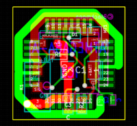
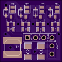
For this thread https://www.rcgroups.com/forums/show....php?t=1921870, I made some brushed MosFet boards to use in micro/nano quads or even planes.

They were specially tailored (except revision C) to be used on this RX https://oshpark.com/shared_projects/BN5Tbq9m done by PLC77 that can be used to make a little Mwii controller.

So for convenience, they can be found here as they began to be lost on the DIY Flysky TX/RX thread.

At a later time, I plan to modify them to :

- get rid of the inductor pads (it's better to have the filtering done on the FC/RX anyway).

- use integrated MosFet packages and redo the layout to reduce size and be more consistent.

All of this wouldn't be possible without the tremendous work of midelic https://www.rcgroups.com/forums/member.php?u=408583. Thank you, mate