Posted by RickC_RCAV8R |
May 27, 2022 @ 10:00 PM | 10,858 Views
Gentlemen :
I LOVE my RCgroup friends . I really DO !
My recent debacle of a communication SNAFU between country states and postal shipping was easily resolved by on e of WE bretheren's parcel tracking apps supplied . Without this simple posting in my screams for HELP , In his issue would have never been resolved . Thanx Jack !
Fellas :
PLEASE help me to understand the concept of 'having NO posts' in one's BLOG . I endeavor to reply to ALL of my readers / critics personally and perhaps paruse their blog postings as well . Far Too Often I am met with 'Zero Postings' within our brother's / members blog pages other than a white , blank screen ! Sure , some of these members have been around our group community site since its inception but have , for some reason , negated their postings .
Now , I AM GUILTY of this sort of practice as well . For me , it was a simple 'weeding out' of materials rarely viewed nor read . Products of dis-interest to be scrapped .
So I just checked my BLOG on the latest 10 viewers to SEE that ALL of these have zero postings on their blogs ! Curious . Is there a blog setting that I have , perhaps missed , reset ? Curious that all of these blogging brothers are all zeroed out . Hmmmmmmmm Just a co-incidence ? Dunno .
Just a curious thing to note , mates . LOVE all of you guys as I can always rely on to obtain timely advice and help upon request . Is that NOT what this group was set up for ? Please rethink about zeroing out your blog stories / posts .
For ALL of my brothers and sisters on RCgroups : Regards and Cheers Mates
Posted by RickC_RCAV8R |
May 26, 2022 @ 07:20 PM | 11,067 Views
Gentlemen :
I am clearly frustrated and 'Pissed' at a purchase I made back in March 2022 of a V22 Osprey from BANANA HOBBY . A beautiful model in the Coast Guard colors . Videos of the model in flight are terrific !
Banana Hobby tends to USE a 3rd Party 'Sub Contractor' for the shipping of International orders . Global Post in this case . Global has a 'Customer Service Rating' which is under 20% ! ! !
As of March 28 / 2022 , this model was transferred by Banana Hobby to the International shipper . As of this posting , there has been NO progress in its shipping to Canada . Seems that this 1st order by myself , seems to be 'Stuck In The System' with no hopes of resolution . USPS status shows that this parcel 'has not arrived' to their facility as it is by the 'sub contractor' . So this order is NOT the fault of Banana Hobby or the USPS as they are not privy to this transportation / handling . Seems to be ALL to do with this sub contractor : Global Post , as I see this .
So what now ? Well , after the currency exchange and shipping charges of Banana Hobby tendered , I am out $394 CDN ! That's What . With NO support and NO way to be able to track this NOR defend my order by claim (Made On Good Faith) , there seems to be no recourse available . Although the purchase of this model was made thru PAYPAL : their position is one to keep shifting my lodged CLAIM further in the calandar . 3rd time now as of this date . NO resolution in sight , I fear . So PAYPAL is not
...Continue Reading
Posted by RickC_RCAV8R |
Mar 17, 2022 @ 03:10 AM | 17,188 Views
Gentlemen :
I have been away for far too long . Health issues , for the most part but am well again . I MISS my rcgroup friends ! .........Really .
Have been working on a ressurected V22 Osprey 100% 'Scratch Build' from foam lately . Started this build nearly 4 years ago but decided to complete this one as the NEW technologies allow for it . 3D printers , high KG output servos , advanced flight controllers , etc. : and some motivation , mates .
An interesting note for this project when started upon is that it would seem as it was 'Divinely Inspired' ! My proof would be as to the exact scale 'fitting' of parts recently purchased like the retracts that , just kinda 'slipped into place' ! Makes a guy feel humble . DIVINE influence at the very least .
Also , my friends on rcgroups have been very supportive of this project . Mike_Kelly donated the PixRaptor flight controller for the V22 from his owned stock ; gratis . I will be dedication the model registration as : C-MKRC in his honor !
Of late , PittSpecial has been working some detail pictures of the landing gear mechanics which I am having many problems in solving . Thanx Pitts !
*********************
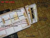
Some pictures of the model along with the LG problems I am trying feverishly to solve . An internal Email noting on the pix between my mate CYNR100 (Dennis) in Cairns .
A 'Taste' , Gents . Something which may inspire an appetite to get off of the sofa and work on a forgotten model .
As usual , Many Thanx for ALL of my readers and friends in this group . Wishing well for all . Cheers Mates !
A few 'tasty bit' in PIX f'ya ALL . Yummmmmmm
Posted by RickC_RCAV8R |
Dec 10, 2019 @ 03:20 PM | 13,008 Views
Gentlemen :
A bit of nostalgia on my part lately recalling my humble start in RC flying back in 1972 when I was a kid . Started with an OS Max single channel pulser in a balsa constructed plane . Learned a lot in those early days about the finer woodworking of balsa construction and was 'blown away' when I could fly a new 4 channel World Engines radio . Wing coverings like MonoKote were in their infancy but I could wager that the use of alternative construction materials and plastics was to become the norm .
As an electronic engineer , I tend to use micro-controllers in a lot of my CNC and test gear designs . I am adept at the programming of these guys and am not opposed to their use for most things . As I fly a lot of multi-rotors , the use of the flight controller is mandatory as there are too many paramenters all changing rapidly during the flight to keep track of . As for fixed wing having micro-controllers to 'soften / compensate' in flight has me wondering though . As these flight controllers more take over the functions , are they aiding the pilot ; or are more of a detriment to the pilot ?
At the peak of my fixed wing days , I was heavily involved with F3A pattern flying still with balsa constructs . Had balsa planes everywhere in the house . Nowadays , only a TeleMaster 60 and a new Scat Cat 500 pylon are the only models which have any modicum of balsa included . Most of the current models are made of EPO or other plastic foams , carbon fiber or 3D
...Continue Reading
Posted by RickC_RCAV8R |
Aug 23, 2019 @ 10:57 AM | 11,375 Views
Gentlemen :
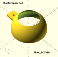
When I do get the chance to fly , the Quanum Chaotic is my recent bird of choice . I have this one (of 3 owned) rigged up with a Walkera DV04 digital camcorder under the nose for some camera work . As I tend to fly this one on 4S power , I am finding that there is plenty of power to spare while even carrying the camcorder and the newly designed 3D printed motor cover pods .
The motor pods have been designed to maintain optimum motor cooling having left the center area open . Escaping airflow can easily exit here . A heavier 2mm shell thicknes printed with a 70% infill makes for a sturdy pod skin which easily handles the landing gear loads .
When printing the lower pods , I noted that there was a central support structure which was kept ! I used a milling bit in my drill press to shorten this structure by about 3/8 " . Before mounting the pod , I used a heavy dollop of silicone on the lower motor mount and the top of this support structure . When the silicone cured over 24 hours , it made a great shock mount pad between the motor part of the frame and the pod support in its interior .
And that's it . A simple and effective addition to the Chaotic which works well .
Regards to my readers and Aussie mates . Cheers RIckC_RCAV8R
Posted by RickC_RCAV8R |
Jan 26, 2019 @ 03:21 PM | 29,282 Views
Gentlemen :
I have been away for far too long and much has happened since my last posting . November saw a month long trip to Cairns Australia to visit my mate Dennis (cynr100) and the club mates with CMAC . This trip was a RC flying and touring trip of a lifetime . Regards to Dennis and the 'boys' who took me in as one of their own . Although I did not fly up to my old levels of competence , I did learn to fly ACRO on the 250mm quadcopter I took along with Dennis' help . He created a monster !
Recent winter shop projects are well along their way . Rebuilds of 2 quadcopters and a Trifecta build have been completed at this juncture . The latest rebuild is of my old V22 Osprey . I always had problems with this one with regards to the nacelle tilting mechs and their setup in the Happy Sundays firmware . A new design around a pair of bargain bin (HK) buggy type 2:1 gear ratio transmissions are at the heart of this . The basic idea is to use these gearboxes to each drive an 7mm fiberglas arrow shaft to do the nacelle tilting . A heavier duty MG995 servo will be used to connect to an intermediate jack shaft to drive the inputs of the gearboxes . Simple 3D printer type GT series gears and belts make the jack shaft to gearbox connections a snap . Future expansions may see a second servo be added to drive each gear mech . For now , I have both being driven with one servo .
All parts so far have been 3D printed for this project . Quick design changes can be realized in
...Continue Reading
Posted by RickC_RCAV8R |
May 29, 2018 @ 02:42 PM | 36,299 Views
Gentlemen :
Been busy in the shop making cabinets lately and setting up a new garden are in front of the shop . Yardwork and gardening does not leave a lot of time for building models or their flying , but since my mate Dennis (cynr100) has laid down the gauntlet in doing a post , here goes .
The DennyCopter ! A Tcopter frame design by Dennis that uses the Rotorbits building system . The 3D print design for this frame was a collaboration effort and used the OpenScad CAD software . Dennis incorporated several features which aids in the connection of the RC equipment and polices up any interconnecting wiring . A major advantage of this frame is that it encorporates a 'break away' design which would minimize damage from any crashes . Although Dennis designed this frame for a typical 250mm sized tricopter , I decided to make a much larger 400mm frame using the central 3D printed mount . My DennyCopter ended up with an AUW of 650 grams which doesn't seem to be out of range as it uses larger motors ans ESCs .
The 400mm DennyCopter uses the Rotorbits yaw mechanism , KK2.1.5 flight controller runnning RC911 A08 firmware , RacerStar BR2216 motors and 30 amp generic type ESCs . This model will be twisting Gemfan 10 X 4.5 props as they worked well with an earlier designed tricopter in the 'YONI' .
The canopy was my design and was added onto later from a basic 'Plain Jane' design I printed earlier . This canopy has 'wrap around' interlocking slot which mates over Dennis' frame on the leading edge spars and fastens by a single screw in its rear . The missile pods of the underside of the canopy are large enough for housing any LEDs up to 5 Watts in their package sizes or a 5 volt laser module with ease .
Kudos Dennis on a great and effective design . I can see why your newbie following is requesting this one as their entry level machine .
Regards to Dennis , my readers and all who tend to push the envelope : RickC_RCAV8R
Posted by RickC_RCAV8R |
Feb 04, 2018 @ 01:30 PM | 46,935 Views
Gentlemen :
Since I received this model last week , I have only had one flight with it as the weather is not co-operating very much . This allowed me to read most of the extensive thread in the Electric Plane Talk forum found elsewhere on this website in the Convergence topic . There are a lot of mods posted in there , some of which are employed here . Although most of these mods are relatively simple in nature , the rear motor mount adapter seen in my previous posting was the major mod shown here . This adapter mod solves the rear motor centering with the rear duct and can only help to reduce , or negate the observed transition shuddering / shimmying seen .
The Mods Performed :
-- Add a VelCro strip in the battery bay to better secure the battery and provide a non-slip mounting .
-- Extend the battery power lead and route thru the forward hole provided for any camera wiring .
-- Use a battery voltage monitor with a high output buzzer .
Set this to trigger at a voltage level high than the
Low Voltage Cut Off .
-- Scuff up the motor shaft ends with emory paper to make for a better grip by the aluminum prop adapters .
-- Add a landing gear skid and secure with VelCro to make it adjustable for CG and overall balance .
-- Dress up the twin tails with customized markings for better visibility .
-- Remount the rear motor with the 3D printed adpter to correct the motor's centered height .
-- Upgrade the linkages with heli grade ball links and re-adjust the center-to-center overall lengths as near to 50mm as possible .
Additional maintenance related aspects were addressed like lubing the linkages and the forward motor mount bearings with graphite .
As with every modeler , performing any mods to a new model is a personal choice . For me , I decided to take the advice of the fellows that posted their thoughts and mods in the Convergence forum . Thanx to all for their experience and observations .
Regards to all of my readers , the flyers , builders and my Aussie mates . RickC_RCAV8R
Posted by RickC_RCAV8R |
Jan 28, 2018 @ 03:17 PM | 37,591 Views
Gentlemen :
The posting yesterday of the rotary tool holder was the pretext for this intended project of a propeller cutter that I named
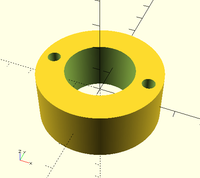
The BullNoser . Although the pictures of this are in my shop's bench vise , the BullNoser is intended to be mounted on a plywood base or the bench top .
I FLY ! I bust a lot of props in the process . Learning the ACRO modes of flying for multi rotors does consume props . If I am lucky and don't bust a complete leaf off of the prop , I usually just zing off the tips in the dirt . Most times , this leaves props which can be shortened to a convenient diameter while ensuring a proper
Bullnose radiused tip . This project makes that operation a snap ! Practically , it takes longer to mount the prop with an adapter to the 3mm center shaft than it does to cut down the prop itself .
A decision was made early on to have the central cross
slider platform be made with a 3mm steel shaft that was salvaged from one of my crash victim motors . This shaft is
press fit into the slider hole with gentle , but firm tapping with a hammer . A standard sized prop adapter is used to secure the prop to be cut down with perfect alignment . The slider IS adjustable for the prop leaf radius and has the ability to be locked into place to ensure accuracy . Future mods for this project would include a measuring rule but is optional at this point in time . Important to NOTE that the
8mm steel rods used for this project were salvaged from an old computer
...Continue Reading
Posted by RickC_RCAV8R |
Jan 27, 2018 @ 03:18 PM | 37,539 Views
Gentlemen :
25,000 reads on my blog . Thanx to all for this recognition mates !
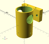
As I am well into the winter build projects , the Anet A8 3D printer is working the majority of the time spent in the work shop . The project presented here is of a Rotary Tool Bench Mount for the Workmate rotary tool . The dimension of the internal sleeve is 49mm which required that I add a layer of electrical vinyl tape arount the rotary tool as a shim . This will protect the tool from the four 10/24 set screws holding it securely in place . The mount has 3/8" holes which may be used to bolt to a plywood base OR the work bench in a strategic location . Having the rotary tool mounted horizontally makes it easier for some jobs .
The project was designed in a few minutes using the OpenScad CAD program . I have included the STL printable file for printing . I hope that it will serve some of my fellow modelers well as it does for me . Any comments or feedback is always welcomed .
Regards to ALL of my readers , my Aussie mates and the builders in RC world . RickC_RCAV8R
Posted by RickC_RCAV8R |
Jul 24, 2017 @ 02:54 PM | 7,962 Views
Gentlemen :
Last weekend saw a day trip with my mate Frank (Mountainrider) to a local hydro transmission corridor east of Castlegar . I hadn't visited this area in quite a few years and was anxious to go . This trip , I decided to take along the
Chaotic quadcopter which I had rigged with a DVR camcorder .
Most of the morning was spent looking for an old trail I hadn't travelled since 1974 when I was in high school . Although , we did find some segments of this original trail , Frank's idea of visiting an alpine lake appealed more . The trip into the mountain side to get to this lake only saw one minor obstacle of a fallen tree which we had to winch ourselves over . The Polaris RAZOR has ample power for performing these types of operations , blazing new trails or going thru mud bogs which we found later on .
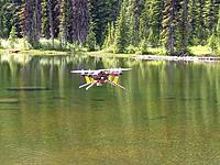
The alpine lake has very impressive scenery in my opinion . After a quick lunch at this small camp spot , I grabbed the Chaotic and stuffed in a fresh battery . I noted that I had a chipped prop from the trip but decided to fly anyway , IF I would take it easy using the throttle . It was a nice uneventful flight over the lake . My thoughts were to weigh the risks of flying over this frigid water temp glacial lake without any floatation installed on the quad and any possibility of having to go swimming for any wreckage .
Frank shot these pix shown here . The flight video did not turn out at all as the memory card in the DVR was toast ! A major
...Continue Reading
Posted by RickC_RCAV8R |
Jan 13, 2015 @ 07:31 PM | 7,629 Views
Gentlemen :
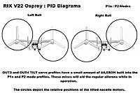
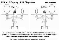
I am doing the final bench testing of the OUTput profile mixes of the Osprey and decided to whip up a set of drawings that may explain the individual goals of each one . They include both flight profiles P1 and P2 and should show what I am trying to achieve .
The OpenAero-VTOL manual found in the first posting within the VTOL section of this website and the firmware manuals on the Steveis blog are also extremely helpful for programming the various parameters needed .
My initial PIDs along with my project notes will be posted soon as I enter in the complete set of flight tested variables . The most difficult TILT servo profiles are consuming a lot of time to get right but should be done in a day or two . Until then , chew on these PID diagrams of the Osprey . Note that the basis pictures for making these diagrams were taken from the web .
EDIT Jan 16 : I am currently reworking the tilt servo linkages in hopes of better dialing in their operation . There is a noticeable amount of slop in the servo itself to deal with . A pair of Tower Hobby M995 metal gear servos and metal servo arms are in the mail as of yesterday . Hence the delay in posting the numbers .
As usual , regards to all of the builders and flyers : RickC_RCAV8R
Posted by RickC_RCAV8R |
Jan 04, 2015 @ 06:17 PM | 7,063 Views
Gentlemen :
If anyone knows where a guy may find a
Programming Primer for the
OpenAero firmware used by the KK2.1 flight controller , please feel free to post it .
As I have written up and modified my initial set of OUTput MIXes for the Osprey several times , I have reverted re-reading the OpenAero manual yet again for more clarity on some issues . The most important concept to understand with this firmware , in my opinion is best stated by
Ran D St.Clair on page 77 of the manual . This sums up the whole thing for me .
"You want to make any necessary trim adjustments first mechanically in the linkages , then in the FC parameters , and almost never in the TX . " (radio)
You bet ! Let the KK2.1 and OpenAero firmware do all of the controlling of the model as it was designed to do . This combination yields mixes that are far superior to any that I have ever encountered by any radio manufacturer anyway . The flexibility of the mixers is impeccable . Follow along any of your model programming while having a copy of this manual handy as it will greatly aid your efforts to a satisfactory conclusion .
RESET your radio for the model that you are working with for all parameters before programming firstly ! No things such as servo travels , direction , mix profiles , throttle curves or duals rates are to be used . Either inhibit or zero out these appropriate values to obtain a "clean set-up" whereby the radio will be transmitting absolutely full
...Continue Reading
Posted by RickC_RCAV8R |
Jan 02, 2015 @ 09:17 PM | 6,763 Views
Gentlemen :
I am starting to program the KK2.1 flight controller (FC) having flashed it with the latest OpenAero firmware . The genius of
Happy Sundays programming is becoming apparent as I go thru the process . The generous channel mixing options coupled together with the required options for setting up motor ESCs or servos are included . So as they state in their excellent blog , why not
use the FC to do all of these functions ! Leave the radio RESET to defaults for your model .
Assuming that the FC is properly flashed , the radio transmitter is RESET to defaults for this new model and that a guy has the model's channel assignments mapped on a copy of the
input / output template , it is matter of inputting the numbers .
Parts 2 and 3 of this blog will cover each of the individual flight profiles in detail with MY NUMBERS and will be posted later . For now , my basic philosophy of the Osprey and why I assigned things as they are .
As the V22 flies in 2 modes of flight , careful consideration must be used to assign the parameters affecting each output channel mix as it transitions between the modes . I want to mix in some aileron input in the thrust motor mixes to create a roll function while in HOVER MODE . A similar mix of throttle and yaw will be used to create a turning function while in the FFF mode . My most complicated mix will be the yaw and forward / back mix of the TILT servos while in the HOVER mode . Getting the percentage of each adjusting input
...Continue Reading
Posted by RickC_RCAV8R |
Jan 01, 2015 @ 06:15 PM | 7,074 Views
Gentlemen :
Linkages . A very important area to focus on for this model , at least . Upon working with these , a couple of weak problem areas did show their ugliness to me . Careful removal of affected obstructed areas cured this problem to all for servo throw travels to be optimized . Other cautions include the use of
swivel link , ball links and the installation of a throw limiting stop bar for the servo over rotation . Once completed , this set-up will be strong enough for the
hover testing as the thrust motors only be driven to angles of attack that are near vertical . Upgrades should be considered to include
extended metal servo arm and metal geared servos .
Bicycle spokes ! I love them for their use as servo linkages . Their threaded ends are of the same type for use with clevises , are a bit heavier gauge than the usual wire and are cheap . The tilt servos have short lengths of the spokes soldered into threaded adapters for the ball and swivel links .
CAUTION : The physics of my tilt solution are already starting to show up even before any flight testing . The standard servo arms had to be extended to obtain a proper travel throw but show a hint of flexing near the end points of the stroke . Use metal ones here . Also , my Futaba S148's have plastic gears in them . Although they move the rotation rods with no problems , power wise ; they will no doubt be strained to the point of stripping as there is a momentum related force of each nacelle present . I
...Continue Reading
Posted by RickC_RCAV8R |
Dec 29, 2014 @ 07:15 PM | 7,179 Views
Gentlemen :
I finally got back into the building after the holiday break and spent a fair amount of time on some of the radio installation and the cosmetics of the Osprey . The bird is in the short strokes as far as the project goes with only the remaining radio equipment , tilt servos and ailerons left to work out . Programming the plane for the V22 mode using the Happy Sundays firmware on the KK2.1 flight controller will be the next major task to complete . I have the mapping of the motors and servos written up already . Hover testing by the weekend , hopefully .
In the meantime , check out these few pix of the Osprey . As usual , regards to all of the builders and flyers . Have a Happy New Year chocked full of happy landings !
Posted by RickC_RCAV8R |
Dec 18, 2014 @ 12:10 AM | 6,341 Views
Gentlemen :
I thought that I had better post these last 2 scans to complete the package . You now have all of the pieces of this puzzle to be able to reproduce this model . If someone with CAD experience would like to clean these up , please do and keep me in the loop .
The recent construction of the Osprey included the fixing of the nacelles to the winglets . I also built up the rotation servo mounts and the ESC mounts . The afternoon saw me doing some soldering of the ESC extension wires that will be required between the wing and ESCs and the outer wing to nacelle motors . The first light filler coat was also applied to the wing . Some epoxy coating to do tomorrow and the final fillings . Paint to come this weekend , possibly .
Should someone attempt this project , please let me know how it is going !
Regards to all of the builders and flyers : RickC_RCAV8R
Posted by RickC_RCAV8R |
Dec 15, 2014 @ 02:26 PM | 6,879 Views
Gentlemen :
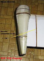
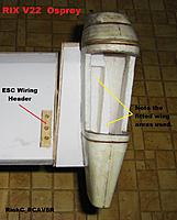
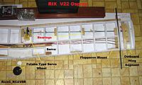
I am very proud to be able to share these pix of the Osprey's wing construction to date as it includes the detail shots of the nacelle rotation system as completed . This rotation system WORKS awesome ! A nearly frictionless bearing / rod system whereby a micro servo can do the rotating of the nacelles . I am opting to use a pair of the heavier standard servos though .
Inspect the detailed pix of the rod system that show how it was designed as they better explain the previous text postings . Please ensure that all of the internal wiring , servo placements and aileron / flapperon hinge mounts are installed before the top wing sheeting is appplied as they will not be accessable later on . Please also note the locations of various cut-outs to enable the modeller access to the final nacelle mounts and actuating servo linkage wheels .
There is a fair amount of cutting and fitting to be done to each of the extended wing portions that attach to the nacelles . Some cutting and sanding of the foam winglets was aided by the careful layout with a French Curve drafting template . Be sure to make a wing profile template from light cardboard of the finally sanded wing to use for marking out the nacelle to be cut away . Layout and cut the wing profile on the nacelle firstly ; trim the winglets next .This same template will be further used to layout the finished wing profile on the wing pod piece . When this pod piece is cut out , it can be epoxied to the top of the wing to form a seamless structure .
Rotation servo mounts and linkages , ESC mounts , Flapperons and forward wing mount will be the next on the list to construct to complete the wing . I continue onwards .
Regards to all of the builders and flyers : RickC_RCAV8R
Posted by RickC_RCAV8R |
Dec 12, 2014 @ 05:35 PM | 7,392 Views
Gentlemen :
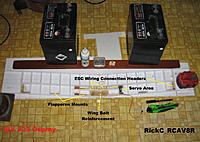
The construction of the wing is proving to be quite easy to do IF each facet is done in order . As the outboard nacelle wing sections will be permanently fixed to each nacelle , they will NOT be removeable ! It is therefore necessary to carefully plan and install any equipment mounts , internal wiring and the rotation rod bearing system BEFORE the top wing sheeting is applied ! The nacelle sections of the wing should be cut thru on their bottoms before the top sheeting is applied as well .
The wing uses some 26 foamboard ribs as well as 2 heavier spruce ones that will be used to permanently fix the nacelles to the rotation rods . Begin the wing construction in the usual manner . Install all flapperon balsa hinge mounts and servo ply mounts next . Cut the internal servo wiring chase and webbing to make a tunnel . Be sure to install a plywood wing bolt piece in the rear of the wing's center . Note the use of my previously posted ESC wiring headers used in the wing . These headers will allow for all of the wiring to remain within the wing but also provide easy connections to the motors and ESCs with standard female connectors . These headers also make for a completely flush connection system .
Use a pair of rotation rod bearings and a 3/16" drill bit to drill each wing rib along the pre-marked rotation rod line and glue in the bearings with each ready-rod / all thread rod , in place . Let the glue completely set before continuing on . Cut thru the bottom wing nacelle sections after the 1/2" x 1/2" leading edges are epoxied in place . Remove the rotation rods and re-install with all locking nuts , washers and servo rotation wheel . Only now , can the top wing sheeting be applied !
The construction of the wing as shown yielded an effective , nearly frictionless nacelle rotation system . Refer to the detailed pix in my blog .
As usual , regards to all of the builders and flyers out there : RickC_RCAV8R
Posted by RickC_RCAV8R |
Dec 08, 2014 @ 12:52 PM | 6,627 Views
Gentlemen :
The Osprey is progressing along very well at this point in time . The work on the wings is underway and is presenting only a couple of minor technical issues to be resolved .
I paid a visit to my buddy Frank (
mountainrider) yesterday morning and showed him one of the engine nacelles that I built . His first comment was about just how light it was . In fact , the whole model shown in the last blog post's pictures has a total weight of exactly one pound as it sits now . More accurately , 450 grams . If I don't go overboard on the wing's construction , the total weight of the model before the electronics installation should come in around a target weight of just over 2 pounds . The pair of 2836's running on a 4S battery supply should make this bird hover with no problems .
It should be noted that I have decided to modify my original nacelle rotation set-up to employ a pair of servos instead of the flashlight guts shown in the last post . The excellent advice of
Ran D St. Clair has shown me the value of using the servos instead . Thanx Ran D ! By going to the servo pair , the model can maintain a useable yaw rate while in the hover mode . This would not have been an option with the system I had originally planned to use . As Ran D also noted , the use of
fixed pitch propellers WILL be an issue that I have to solve as the physics becomes a major factor . It may be necessary to employ a tail motor / prop in the elevator to solve this issue . We shall see .
...Continue Reading
 Views: 202
  Views: 207
  Views: 197
  Views: 185
  Views: 192
  Views: 232
  Views: 198
  Views: 195
 Views: 201
Views: 207
Views: 214
Views: 206
Views: 197
Views: 215
Views: 198
Views: 241
Views: 225
Views: 238
Views: 244
Views: 225
Views: 244
Views: 237
Views: 242
Views: 223
Views: 228
 Views: 208
  Views: 205
  Views: 234
  Views: 192
 Views: 202
Views: 207
Views: 194
 Views: 213
  Views: 110
  Views: 121
  Views: 121
  Views: 117
  Views: 109
  Views: 122
  Views: 132
  Views: 108
 Views: 130
Views: 127
Views: 146
Views: 112
Views: 113
Views: 103
 Views: 132
  Views: 121
  Views: 147
  Views: 168
  Views: 133
  Views: 135
  Views: 128
  Views: 124
  Views: 107
  Views: 130
  Views: 120
  Views: 105
  Views: 91
  Views: 91
  Views: 97
  Views: 95


