Charles B's blog View Details
Posted by Charles B | Sep 17, 2011 @ 02:51 PM | 14,230 Views
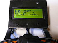
Here is the Arduino program for the FrSky display interface we made using the
Arduino Min Pro 328.

We updated it so it does a Auto ZERO current Cal. on first power up. That nulls out
the offset of the current sensor at the low end of its current reading.

This version also has a small menu so you can change the battery capacity
that in the plane. It store that into EEProm memory for the next time you power up it will restore you last setting.
Posted by Charles B | Sep 12, 2011 @ 05:06 PM | 14,975 Views
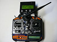
I've been working on my Control box for a while and this what we ended up with.

The HK-T6A doesn't have any original Electronics in it at all.
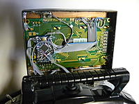
We pulled the Tx and control board. Replaced the control board with a
MicroStar2000 board and replaced the transmitter board with the FlyDream DIY transimitter. Had interference causing loss of signal to many times. We pulled out 8 Rx's and ordered the FrSky units. So far it has work 100% with no drop outs.

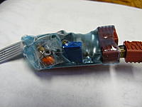
We made a interface to the transmitter to read the telemetry data for our planes. I added a home made current/voltage board for our 8 receivers. It is sure nice to see the voltage and current used during the flight.

Much thanks to c2po RCG user for some mods to the FrSky Tx.

His link is
https://www.rcgroups.com/forums/show....php?t=1478825
Posted by Charles B | Oct 24, 2010 @ 10:24 AM | 14,218 Views
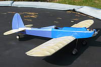
We got this unfinished Plane and have been flying it it's a great little
flier. The Wing is 50 inch and it has 32 inch length.
Does anyone have any idea of what it is and who made it ?

Yes we made it Electric .
Turnigy SK3536 310 watt motor
4S1P 2200 ma.
10 x 7 Prop.
It gets around 15 to 25 minutes of flying time.


We would like to find another KIT like it . If one is around .
Posted by Charles B | Aug 07, 2009 @ 09:09 PM | 15,657 Views
multiple switches on one channel

Here is a Basic program the takes on servo input at the TX and makes a

PWM output to be able to have 5 separate switches in one servo channel.

This program was wrote in Basic with the OSHON SOFTWARE for a Pic.

You could use any Pic from 16F84a up . The Pic don't need AtoD or any thing fancy.

Here is the Tx part.

Define CONF_WORD = 0x3f38
Define CLOCK_FREQUENCY = 4
INTCON.T0IE = 0 'DISable Timer0 interrupts

TRISA = 0x1f 'set RA0, RA1 , RA2 ,RA3 and RA4 as inputs, other PORTA pins as outputs
TRISB = %00000000 'set PORTB pins as outputs
CMCON = 0x07 'set the CMCON to 7 for the compare.'rem only need on some Pic's
Dim length As Byte
Dim bout As Byte
Dim binout(8) As Byte
Dim i As Byte
Dim x As Long
x = 3 'rem set 3 for 5 bits/switches set to 6 for 4 bits/switches
'rem 3 is 30us in time. this allows 30us of jitter/noise.
For i = 1 To 5
binout(i) = x 'rem setup the lengths of each bit/switch
x = x * 2
Next i
AllDigital
PORTB = 0
loop1:
length = 0
'rem look for the servo pulse for the channel you wish to replace with switches.
If PORTA.7 Then 'rem is it time for the switches ,input PWM
If PORTA.4 Then length = binout(5)
If PORTA.3 Then length = length - binout(4)
If PORTA.2 Then length = length - binout(3)
If PORTA.1 Then length = length - binout(2)
If PORTA.0 Then length = length - binout(1)
ServoOut PORTB.1, length 'new PWM per switches
Endif
Goto loop1
End...Continue Reading
Posted by Charles B | Sep 18, 2008 @ 11:10 AM | 17,523 Views
Here is one of my playing around projects that I've been trying different
things with a GPS module.

I'm using a Stamp BS2 CPU to make it easy to program and see what we have
to do with the NMEA sentence information. We ended up using the
$GPRMC gives us the UTC Time, Lat., Lon. Direction going ,speed and the
$GPGGA sentences gives us the elevation and the number of Satellites the module is receiving.

Here is a good link for the NMEA sentence http://home.mira.net/~gnb/gps/nmea.html#gprmc


The GPS module is a ISM_300 C4 module from Inventek Systems they cost $30.
The small CPU is a basic system BS2 Stamp from http://www.parallax.com/ .
The BS2 send its info to a serial port to a windows
system with a VB6 program . That program generates the XML file that
is used by Google Earth. It will show you your log info.


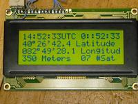
Here is what the LCD 4 x 20 display looks like.
https://static.rcgroups.net/forums/i...attach/jpg.gif

The LCD shows the Lat. and Lon in Degrees, Minutes and Seconds.
it is from the SGPRMC sentence that is in the DDMM.MMMM format.
the stamp converts it to the other format.


Here is the circuit of the GPS project.

https://www.rcgroups.com/forums/show...=2070653&stc=1


You can download the Basic program from . Do a right click and select "save Link as" to save the file.

http://home.roadrunner.com/~cbeener/GPStoPC.bs2

The next step I'll be adding a MMC memory stick to the project to turn it into a stand alone data logger. At some point I'll remove the stamp module and make the CPU a Pic or an AVR .

We have the VB6 program making the KML file now. But we have some programming on the VB6 program to clean up. It will have to wait for a posting. I'm in the process of making it plot the path you have travailed on its program.

CBeener