Archive for May, 2015
Posted by MassiveOverkill |
May 11, 2015 @ 10:04 AM | 63,063 Views
In our effort to stop the senseless killing of inanimate objects  , we continue our series of saving more innocent victims of our precious hobby.
Many motors come with multiple sets of motor mounting bolts. Most of you who've never done this before will gravitate towards the longest bolt sets because as many of us are males, we will cater to our machismo. Some will select the longest bolts simply because our mechanical experience tells us it will give a better anchor.
Arm widths can vary in thickness so that's why multiple bolts are supplied to accomodate. You should ALWAYS check to make sure when your bolts are tightened all the way down they're not trying to impale the hard-working and very innocent motor coil.
Here you can see a bolt that's too long installed:
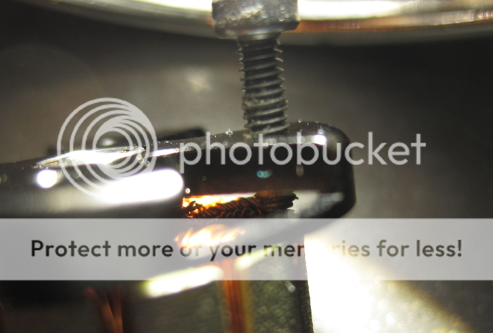
And the resulting damage and slaughter of the innocents:

If you're lucky, and you didn't actually sever the coils like in the above photo, you can possibly still salvage the motor by making sure that the short only existed when the bolt was touching and you didn't damage the stator tooth, reapply some nail polish or shellac to the coils to re-insulate them and apologize profusely for your transgression.
, we continue our series of saving more innocent victims of our precious hobby. Many motors come with multiple sets of motor mounting bolts. Most of you who've never done this before will gravitate towards the longest bolt sets because as many of us are males, we will cater to our machismo. Some will select the longest bolts simply because our mechanical experience tells us it will give a better anchor.
Arm widths can vary in thickness so that's why multiple bolts are supplied to accomodate. You should ALWAYS check to make sure when your bolts are tightened all the way down they're not trying to impale the hard-working and very innocent motor coil.
Here you can see a bolt that's too long installed:
And the resulting damage and slaughter of the innocents:
If you're lucky, and you didn't actually sever the coils like in the above photo, you can possibly still salvage the motor by making sure that the short only existed when the bolt was touching and you didn't damage the stator tooth, reapply some nail polish or shellac to the coils to re-insulate them and apologize profusely for your transgression.
Comments (8)
Add Comment
Posted by MassiveOverkill |
May 01, 2015 @ 12:42 PM | 64,167 Views
I'm writing his tutorial because our new Emax bundle now includes OneShot ESCs capable of doing 4S. As a result, we've chosen to go with ESCs without BEC (Battery Eliminator Circuits), due to most BEC circuits being of the linear type, which are inefficient and generate heat vs switching circuits which are more expensive and not commonly found in ESCs with an integrated BEC circuit. I've received many questions on how to wire up a dedicated BEC so I thought I'd show a tutorial on how I do it as well as showing how to wire up the other components we sell.
Below we have a layout of one of my typical installs. Please note the 5V BEC regulator isn't actually soldered to the PDB but I've placed the wires in the appropriate positions of where you would solder them. Also note that I don't have the ESC power wires soldered to the PDB as this is a mockup. I may replace this picture with something more accurate at a later date.
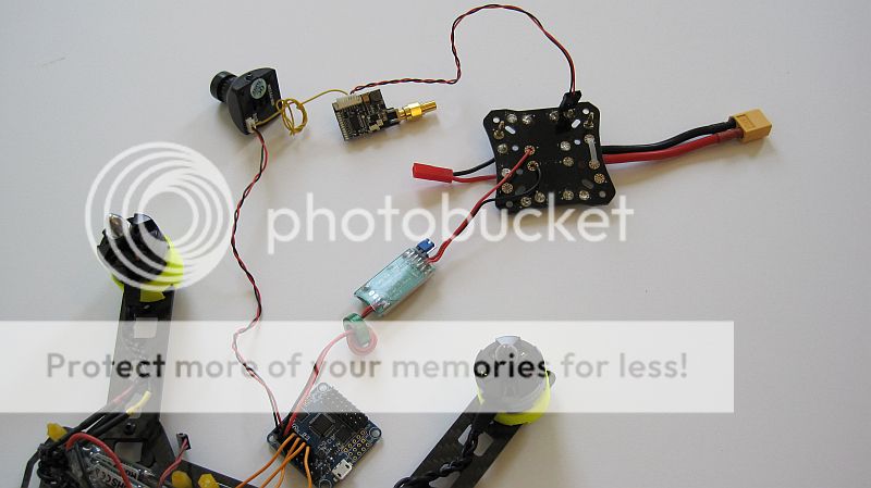
Essentially in the above picture we have:
1) PDB which has been tapped for directly voltage from the LiPo as well as our BEC module attached. As previously mentioned our ESCs would also be soldered
2) Going clockwise we have our dedicated BEC\Voltage regulator which then feeds our FCB via any of the spare servo\motor output channels
3) From the FCB we feed our wide voltage FPV camera (HS1177) through the other open servo motor channel. Note that you should only plug low amp draw devices into your FCB for power such as your receiver or...Continue Reading
Below we have a layout of one of my typical installs. Please note the 5V BEC regulator isn't actually soldered to the PDB but I've placed the wires in the appropriate positions of where you would solder them. Also note that I don't have the ESC power wires soldered to the PDB as this is a mockup. I may replace this picture with something more accurate at a later date.
Essentially in the above picture we have:
1) PDB which has been tapped for directly voltage from the LiPo as well as our BEC module attached. As previously mentioned our ESCs would also be soldered
2) Going clockwise we have our dedicated BEC\Voltage regulator which then feeds our FCB via any of the spare servo\motor output channels
3) From the FCB we feed our wide voltage FPV camera (HS1177) through the other open servo motor channel. Note that you should only plug low amp draw devices into your FCB for power such as your receiver or...Continue Reading
- User Lists


