|
|
|
|
|
I use both ACad and Draftsight (Draftsight because I can't get my ACad loaded on Win7). ACad is on an older XP. Both systems work practically the same.
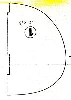
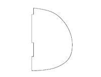
First, import a raster image (I use either jpg or tiff images) into my drawing assigning it to it's own layer. Second, rotate (if necessary) the image to achieve a true horizontal reference. If there is a known dimension on the plan, the image can be re-sized at this time. Can be changed later if necessary. Third, I do my tracing on Layer O. Trace out a few lines, then hide the raster layer to see how the tracing is looking and what else I might need to trace. Some CNC or Lazer cutters seem to have problems with splined lines, so a trick I use for smoothing up curved lines is to use the polyline tool to first trace the curved line using fairly large steps. Then spline that line. Select the line and adjust the handles so that the line closely follow the original plan. More handles can be added if necessary. Then turn on Snaps with "Nearest" selected. You don't want any other snaps on and you want ortho off. Trace around the splined line using the polyline tool again but use very small steps. The snap setting will hold you right on that splined line. This second tracing goes very quickly with the help of the snap setting. Delete the splined line. You now have a polyline that the cutters can work with. |
|
|
|
|
|
|
|
||
|
|
Quote:
|
|
|
|
||
|
|
|
|
|
Rob,
That's effectively what I do but I end up with a polyline with very short segments . As I'm not a CNC or Lazer operator maybe you can answer this.....does your cut follow the curve of a spline or does it cut to the handles? I've been told that some machines can't handle a splined line at all....but I'm not sure. I know my method seems to work well. Don |
|
|
|
|
|
||
|
|
Quote:
My laser and CNC will cut curves and splines fine. I have, however, recieved files from others that upon inspection the line segments were drawn wrong, which makes the cut look wrong. I think it comes down to how you draw it. I had a heck of a time getting sketchup files to work right even exported as a dxf. Never heard of a CNC not being able to cut a curve or spline, it's all in the G-Code. If you want a curve, draw it as a curve not a bunch of rotated straight line segments. |
|
|
|
||
|
|
||
|
|
Quote:
Don't want to belabor the point but maybe an explanation based on the picture below will be easier for an old man to understand.....lol Line 1 is a three segment polyline. Line 2 is a copy of Line 1 that has been splined. Notice that the handles in both cases have not changed position. If the lines were overlayed the handles would be in exactly the same spot for both lines. The dashed lines are merely reference lines. If you were to cut Line 1, I'm sure you would end up with three straight line segment cuts based on the handles. No problem so far....  Now, if you were to cut Line 2, which clearly shows as a curve on the drawing, would you end up with a curved cut or the same cut line as Line 1 based on the handles? Does your machine follow the curve shown or the handles? Guess I went ahead and belabored the point but I do appreciate your patience with this question. TIA, Don |
|
|
|
||
|
|
||
|
|
Quote:
|
|
|
|
||
|
|
||
|
|
Quote:
Thanks for the reply. ooops, can't find your email but sent you a message requesting same from your site.... |
|
|
|
Last edited by Brner; Jan 07, 2013 at 05:00 PM.
|
|
|
|
|
|
|
Ok, Here is what I found.
1.the Draftsight DXF is not a direct import into the laser software. I had to open the file in AutoCad and convert it. No big deal but worth mentioning. 2. after importing, the line #1 looks as drawn but line #2 was all wacky. I had seen this before and knew how to fix it. I had to explode line #2 into arc segments. 3. After fixing line #2 both went through the laser just fine and were cut as shown. I forgot to take a picture but they cut exactly as they were drawn above. In conclusion, both ways will work fine but line #2 was more refined as it was drawn smoother. The "handles" concern became moot because I exploded the arc and removed the associativity (sp). Let me know if any of this does not make sense or needs clarified. It's always good to learn something new, lol. Rob |
|
|
|
|
|
|
|
|
Rob,
I've been playing with this most of the night and found pretty much the same as you did. 1. The problem with opening the DXF may have just been the format I saved it in. As with AutoCad there are many DXF versions (14 to be exact) that one can save to. I wasn't sure which format to use but I believe I saved it to R14ASCII Drawing. 2. I also found that by exploding line 2, it exploded into many "straight" line segments with all the handles following the line. Not sure how you got it to explode into arc segments....might not be available in Draftsight but I'll check my Acad program later for that function. Handle to handle seems to be the way the cutter works. Another thing I read on your website is that ellipse's should not be used. Understandable if the cutter goes from handle to handle. I did find a work-around for this too. As I like to use ellipses a lot I'll put this solution in another post. As you said, it's always good to learn something new... Don |
|
|
|
|
|
|
|
|
I would like to use DevCad to get my ATR 42 plans into files for cutting.
The scan comes out with a lot of background "noise" and when I preprocess it just puts too much stuff on the background image. Any suggestions for cleaning up the image so just the actual part is enhanced? |
|
|
|
|
|
|
|
|
David,
At first glance it looks like you are trying to export a jpg that you've loaded into your Cad program....disregard if I'm wrong here. I'm not a DevCad user so can't say what that program can do but here's a quick look at what Draftsight and Acad can do.... I pretty much followed my first post on tracing with a couple of tips learned from my exchange with Rob... No dimensions were given so it's not to scale but could easily be re-sized.... Look around DevCad and see what tools are available for tracing over a jpg. Don |
|
|
|
|
|
||
|
|
Quote:
The thing is that all the shadows and everything show up in the Auto-Trace. I wonder if there is any way to "bring to the front" the acutal lines I want and ignore the shadows. |
|
|
|
||
|
|
||
|
|
Quote:
My only other contribution to this (having done a lot of these conversions) is that it works better zoomed out. Most people, including me when I started, zoom in too close to the bitmap they are tracing. |
|
|
|
||
«
Previous Thread
|
Next Thread
»
| Thread Tools | |
| Similar Threads | |||||
| Category | Thread | Thread Starter | Forum | Replies | Last Post |
| Help! | Selecting objects in AutoCad | jcyr1 | CAD/CAM | 8 | Oct 08, 2012 08:37 AM |
| Discussion | Need plan, 3D view or Autocad On F/A-18C | X-spec | Electric Ducted Fan Jet Talk | 1 | Dec 23, 2005 05:37 AM |
| Question | Importing jpeg,bmp,etc->tracing in Autocad 2005 | mrbaseballny | The Builders Workshop | 2 | Jan 08, 2005 12:37 AM |
| Autocad & 3-views question | mad mike | Electric Plane Talk | 2 | Aug 23, 2003 10:59 PM | |
| getting former section from a 3 view -Autocad | mitchamus | The Builders Workshop | 5 | Jun 09, 2003 06:20 PM | |


