peterangus's blog View Details
Posted by peterangus | Dec 28, 2013 @ 05:44 PM | 9,584 Views
Power Required, weight, and speed, for a scaled-up model
BLOG 019

Let's say we have a favourite model, and we would like a larger version.
By employing these scaling laws we can quickly predict the important parameters of the larger version [power required, weight, speed], based on the parameters of the datum model.

I am looking here at these three different laws:
--------------------------------------------------------------------------------------
Law 1.....wing loading does not change with linear size
The larger model will fly at the same speed as the smaller. This will give the appearance of slower flight. Structures become less robust as size goes up.
---------------------------------------------------------------------------------------
Law 3.....wing loading proportional to length squared
This gives scale speed [double the length, double the speed].
Be aware that the power required can increase dramatically.
------------------------------------------------------------------------------------------
Law 2...........wing loading proportional to length
This law tends to produce designs which are nearer-to-practicable than laws 1 and 2.
-----------------------------------------------------------------------------------------
The laws ensure that the parameters [length, power, weight, speed] remain in a correct relationship to each other. But there is no guarantee that they will result in a practicable model.
Posted by peterangus | Dec 05, 2013 @ 03:27 PM | 9,720 Views
BLOG 018
I think it is true to say that we normally choose the propeller after deciding on the motor. But if we decide to use a scale propeller , then we are reversing that sequence. The propeller is chosen before deciding on the motor.

Here I present a possible methodology.

step 1...........choose the propeller

step 2........choose a pitch speed appropriate to the model's intended max flying speed.
In the absence of better data, use my BLOG 009 as a guide

step 3...........calculate propeller rpm
rpm = pitch speed [mph] x 1053 / pitch [inch
[All power-related parameters are at WOT]

step 4...........calculate no-load rpm
no-load speed = prop rpm / .75
[I am assuming that prop rpm = 75%NLS]

step 5...............calculate the required motor Kv
motor Kv = no-load rpm / motor supply volts

step 6..........determine shaft power to drive propeller
If you know the prop's power characteristic the power can be calculated.
If the prop is listed in Drive Calc [or similar] you can contrive to extract this power value.
If you have a dyno, and the prop, run a test.

step 7...........calculate battery power to drive propeller
battery power = shaft power / .67
[I am assuming that motor efficiency at 75%NLS is 67%]

step 8...........determine the battery power required, based on the model's weight
Use my BLOG 008 as a guide

step 9..............calculate the required motor weight
Use the higher of the two battery powers [steps 7 and 8] .
motor weight [grams] = battery power [watts] / 3 watts per gram.
[I am assuming that at 75%NLS, the motor IN power per gram of motor weight is 3w/g]

step 10...........pick a motor
Search the vendors' lists for a motor which has the required weight [step9] and the required Kv [step 5].
Posted by peterangus | Oct 11, 2013 @ 03:27 PM | 10,183 Views
BLOG 017

Example:
At 10 inch pitch and 10,000 rpm, the pitch speed is 95 miles per hour.
Posted by peterangus | Aug 11, 2013 @ 04:35 PM | 9,961 Views
BLOG 016

I managed to damage my new PBY on its first outing.

I had set the ailerons "by eye" [inaccurately], and this made the model difficult to control.

Careful re-rigging of the ailerons, using marker boards, produced the needed improvements.

span 60"......weight 36 oz.......wing loading 11 oz /sq ft......two 40 gram bell motors,1500 Kv............batts 3S, 2.2Ah
************************************************** ***************************************

Four years since the Sunderland last was airborne.

I was apprehensive. I should not have worried. It displayed its usual impeccable manners.
************************************************** ***************************************

The Hunter is flying well, but landings are dangerously fast. An airbrake may be the solution.
************************************************** ***************************************

My 24-year-old B52 had its annual flight on a chilly October morning. Made me think about winter projects.
Posted by peterangus | Jul 16, 2013 @ 06:47 AM | 10,450 Views
BLOG 015

Here are drawings for an easy-to-make torque balance.

Materials are.........aluminium L section...........steel rod.........wheel retainers...........timber.........hardboard.

Related threads:
https://www.rcgroups.com/forums/show...25#post5065888
https://www.rcgroups.com/forums/showthread.php?t=978958
Posted by peterangus | Mar 16, 2013 @ 05:27 PM | 10,333 Views
BLOG 014

************************************************** **********************************

NOT ONE of my 25 flyable models has a nose-mounted motor.

A solid nose is much more durable.
************************************************** **********************************

My balsa models have no open structure. And no covering.

No film. No tissue. No glass.

Finish is paint on wood. Filler + non-shrink dope + colour + matt varnish.

Easy to repair.
************************************************** *********************************

I never use bullet connectors.

Power Poles on battery. Elsewhere, I solder wire-to-wire.
************************************************** *********************************

For motor and servo extension leads, I use single-strand, varnish-insulated winding wire.

Neat......compact..........light..........cheap... .......
************************************************** ********************************

I like rubber-band attachments. But I've never bought large "wing bands".

Photo shows a set of wing bands for my 60" PBY.
Name: pby 003.jpg
Views: 277
Size: 94.4 KB
Description:
************************************************** ********************************
Posted by peterangus | Mar 01, 2013 @ 07:43 AM | 11,686 Views
What factors determine the best operating voltage for a motor?

BLOG 013


One of the few really-useful bits of information that we find in vendors' motor specs is the recommended voltage. [ usually stated as, for example, ......2-3S..........3S......4-6S...]

We are dependent on the vendor for this information, since there are no other clues to the best voltage, which might be anywhere between 3v and 60+ v.

When choosing a motor for a particular application, it is essential that we know the best voltage for each motor on offer. A battery voltage lower than the motor's best voltage will always produce a lower power output. A higher battery voltage will result in motor overheat or some related complication.

************************************************** ************
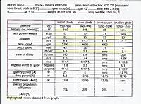
To understand the effects of supply voltage, let us imagine a series of test runs with a motor, at supply voltages of say, 3.5, 7.0, 10.5, 14.0, 17.5, 21.0v, and so on.

At each voltage, fit a prop which slows the motor to 75% of its no-load speed [at each voltage the no-load speed and the prop size will be different]

Each run to be continuous, with wide-open throttle; say 5 minutes duration.

Cooling arrangements: exposed motor, tractor prop, 20C ambient.

On each run, the motor temperature, starting at ambient, will increase as the seconds go by, and after two or three minutes it will stabilise at a steady value.

With each step-up in voltage, there will be an increase in the...Continue Reading
Posted by peterangus | Jan 20, 2013 @ 08:08 AM | 11,253 Views
BLOG 012

Progressing well. Should fly in April.
Posted by peterangus | Jul 14, 2012 @ 11:10 AM | 15,028 Views
BLOG 011

This thread will be much easier to follow and understand if you have prints of the 3 attachments to hand for ease of reference.
An alternative [better?] title for this thread could be "Typical characteristics of e-flight motors"


In this thread I attempt to show how a typical motor behaves with different loads. That is, with different size props.

All values relate to full-throttle operation. Speed variations result from fitting different-size props.

The motor used as an example is a 39 gram outrunner with a Kv of 1501rpm per volt. The supply voltage is 10.5, in accord with the maker's recommended 3S.

The horizontal axis of the graphs is motor speed, expressed as a percentage of the no-load speed.

The shape of the power curves is aproximately correct for any motor at any voltage, but of course the numbers for power, rpm, and prop size, refer only to the example motor.

The shape of the efficiency curve is typical, though the peak value and its %NLS position can be slightly different for other motors.

Name: motortable2.jpg
Views: 484
Size: 103.4 KB
Description:


Name: dddd.jpg
Views: 625
Size: 46.6 KB
Description:

...Continue Reading
Posted by peterangus | Mar 28, 2012 @ 12:37 PM | 12,818 Views
BLOG 010

Lohner L
Name: Lohner-3.jpg
Views: 375
Size: 24.2 KB
Description:


Supermarine PB31.......Crashed on take-off. Repairable.....I must remember--don't reduce take-off power until level flight established....Elevator response is poor when propwash is slow.
Name: x06 009.jpg
Views: 315
Size: 136.4 KB
Description:


Tu95. As designed, the engine nacelles were attached to the wing with a complex arrangement of hidden rubber bands, which required frequent replacement. Bands now replaced with thin soft steel wire: much less trouble. "Knockoffability" proved to be unnecessary.
...Continue Reading
Posted by peterangus | Jan 30, 2012 @ 02:26 PM | 12,979 Views
BLOG 009...........follows from blog 007

Print the attached graph, and draw a vertical line at the model's wing loading, and note the pitch speeds where the line intersects curves A and B.

Any speed between curve A and curve B will probably be flyable.

The spots represent some of my models, which fly OK.
Attachment 4594028
Posted by peterangus | Jan 29, 2012 @ 12:44 PM | 13,808 Views
BLOG 008................follows from blog 007
  • Print the attached graph
  • mark the model's wing loading [vertical line].
  • Choose a point on the line to indicate the performance level [agile / sedate].
  • Read off the watts per pound.
  • Multiply the watts/lb by the model weight [lb] to produce a power figure [watts]. This is the battery out power required.

The graph relates to a typical clean monoplane. You must make your own allowances regarding draggyness and speed required.

It helps if you "spot" a few of your own existing models on the graph.

Name: agsed.jpg
Views: 446
Size: 96.4 KB
Description:
Posted by peterangus | Jan 29, 2012 @ 11:25 AM | 14,974 Views
BLOG 007

Overview

This is how I select a power train. It's not a universal solution, but it suits my style of flying.

My style..........prop driven scalish models.........motors from 15 grams to 70 grams........wing loading from 10 to 20 ounces per square foot.............run time [with throttle usage] 14 minutes per charge............all 3S batteries and 3S motors..........no prop hanging...........no unlimited vertical...........no super speeds.

The process in brief
  • Estimate the model's all-up weight
  • Decide the power and pitch speed required by the model
  • Search for a combination of motor, matched propeller,and battery, which provides the required power, pitch speed, and run time.

Estimate the all-up weight of the model

Establish the bare weight [weight with no power train] .

Make your best estimate of the power train weight, and add to the bare weight, to give an all-up weight.

In the absence of better data, assume power train weight to be 40% of bare weight.

Calculate the wing loading

Decide on the power required by the model. Refer to BLOG 008.

Decide on the pitch speed required by the model. Refer to BLOG 009.

We must now find a combination of motor + matched propeller + battery voltage which can provide these chosen values of power and pitch speed.

Vendors' specs do not provide enough info to make a definite choice, but they do enable us to pick a "candidate" motor. By "candidate" I mean a motor which has a...Continue Reading
Posted by peterangus | Jan 13, 2012 @ 12:39 PM | 13,403 Views
BLOG 006
The model was fitted with EagleTree logger V2. Parameters recorded were: altitude,,,,rpm,,,,battery volts and amps,,,,airspeed.

The flight was planned to incorporate a period of unpowered shallow glide, and a period of powered level flight, both at the same airspeed.

The efficiency calculation is based on the proposition that drag x airspeed is the same for the glide and for the level flight, and that it is equal to the power provided by gravity during the glide [=model weight times descent rate]

Overall propulsive efficiency worked out at about 20%.
Name: test graph.jpg
Views: 397
Size: 106.9 KB
Description: Graph of flight data. date 18 Sept 2005.

Name: table_FANo1.jpg
Views: 376
Size: 284.7 KB
Description:

...Continue Reading
Posted by peterangus | Feb 25, 2011 @ 03:17 PM | 14,614 Views
BLOG 005..........follows from blog 007
How to find a prop which matches the motor, and how to decide whether the matched prop + motor combo suits the model.

Match prop to motor
To get the best from your electric power system, the propeller has to be accurately matched to the motor.

This note describes an easy way to do this. A tachometer and a wattmeter are required.
--------------------------------------------------------

The speed at which the motor runs depends, amongst other things, on the size of the prop. As would be expected, a larger prop results in a lower speed.

Running with no prop results in the highest speed at the chosen voltage, referred to as the no-load speed [or NLS] for that voltage. Fitting a prop will produce a lower speed.

This slowdown effect from no-load speed is utilised here to determine which prop best suits the motor.
---------------------------------------------------

My flying style [as described in Blog 007] states "run time [with throttle usage] 14 minutes per charge". This equates to about seven to ten minutes at full-throttle.

With this run time, it is best to use a prop which slows the motor by 26% of its no-load speed [ie; to 74% NLS]. This results in the lightest power train [motor plus battery etc], and usually no overheat. Some tollerence must be allowed: say 74% to 78%...Continue Reading
Posted by peterangus | Feb 06, 2010 @ 06:28 PM | 15,039 Views
BLOG 004
The motors available for e-flight vary greatly in size and speed, but in some respects they are all remarkably similar.

Most motors [say, between 1oz and 10oz] can be described by the attached graph, which relates efficiency, power-to-weight, and speed.
~~~~~~~~~~~~~~~~~~~~~~~~~~~~~~~~~~~~~~~~~~~~~~~

The efficiency curve mostly coincides with the %NLS line, but it falls below this line as no-load speed is approached. In discussions, unwarranted significance is often accorded to peak efficiency. Much more important is the efficiency at the actual operating speed. That efficiency varies little between comparable motors.
~~~~~~~~~~~~~~~~~~~~~~~~~~~~~~~~~~~~~~~~~~~~~~~

The output power-to-weight values will differ between motors, but the shape of the curve is always similar. The peak always occurs at about 50% to 55% of NLS. This parameter is just as important as efficiency, but it is rarely [never?] mentioned in the motor guides.
~~~~~~~~~~~~~~~~~~~~~~~~~~~~~~~~~~~~~~~~~~~~~~~

Peak efficiency [which occurs at about 85% to 90% of NLS] implies low battery weight, but it incurs high motor weight.

Peak output power-to-weight [which occurs at 50% to 55% of NLS] implies low motor weight, but it incurs high battery weight.

Neither of these peaks is a good operating point for typical models. The best compromise occurs at some intermediate %NLS value. This is demonstrated by my BLOG 002 "Power-to-weight ratio for the complete power train".
Name: same.jpg
Views: 619
Size: 54.5 KB
Description:
Posted by peterangus | Sep 11, 2009 @ 03:11 PM | 14,366 Views
BLOG 003
The most important motor performance parameter is OUTPUT POWER.

More specifically: at a stated voltage, and with normal cooling, the maximum continuous output power which can be obtained without overheating.

This important parameter never appears in manufacturers' data.

And it is only rarely mentioned in the pages of RCGroups.

If advertised data included this parameter, it would be a great help in choosing a motor.

If customers demanded it, it would be provided. There are no technical obstacles.
Posted by peterangus | Jul 31, 2009 @ 10:39 AM | 15,538 Views
BLOG 002
I have done a study, with interesting results, which are shown in graph 1. The motor data is taken from graph 2. The computation is shown in the table.

By "complete power train" I mean motor+prop+ESC+wiring+battery.

Please note the % no-load speed at which the best power-to-weight ratio occurs. 70%NLS for a 5 minute WOT motor run. 74%NLS for a 10 minute run. 78%NLS for a 20 minute run. 80%NLS fof a 40 minute run.

Note that peak efficiency is not a good operating point unless you are into long motor runs.

Graph 3 shows an example of how the data translates into powertrain weight for a particular application.
Name: bor.jpg
Views: 600
Size: 77.8 KB
Description: GRAPH 2

Name: ptwt.jpg
Views: 636
Size: 97.4 KB
Description:

...Continue Reading
Posted by peterangus | Mar 02, 2006 @ 07:02 PM | 17,151 Views
BLOG 001
There is a large ammount of cell data in these forums.

As a user of cells, I find that most of this data is incomplete and unconvincing. And what good data there is, has to be processed to make it usable.

Some suggestions in the attached file.
best.doc