NoFlyZone's blog View Details
Posted by NoFlyZone | Dec 10, 2010 @ 11:04 PM | 90,374 Views
Mr. Richard Feder, of Fort Lee New Jersey writes:

Dear NoFlyZone,

I am totally confused by all the various claims made by vendors of motors as to what they mean when they speak of "continuous current" and "burst current" specifications. What the heck do these two terms above mean anyway? And is there some way that I can put aside the exaggerated claims made by some vendors and have a way of looking at these terms that makes sense to me, as a beginner?

Hi Richard,

Yes, there is a way we can make sense of all this mess! Let's look at what we mean when we say "continuous current" and 'burst current".

to be continued.....
Posted by NoFlyZone | Dec 04, 2010 @ 02:26 PM | 96,256 Views
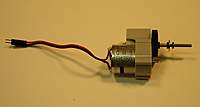
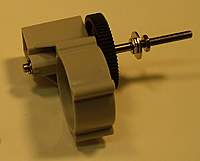
For newcomers to RC planes, the most popular motors sold are outrunners. These are certainly nice motors that will work in lots and lots of planes. The only drawback, though, is that when we desire a lower rpm from our motors, we find that the lower the rpm in motors, the heavier the motor becomes. This is because high rpm motors are wound with few turns of copper wire, while the low rpm motors are wound with lots more turns of that copper wire.

Oftentimes then, what we do is simply use one of those high rpm motors, and use a gearbox to reduce the motor's effective rpm.

We'll now look at a typical motor and gearbox combo, and describe all the parts, and what they do.

First I'll put up the pictures we'll be using, then in the next post, we'll look at them closely.

If you're reading this from my Blog page, the rest of the tutorial is here.
Posted by NoFlyZone | Jun 09, 2010 @ 08:28 PM | 98,883 Views
A few weeks ago, I picked up an MS Composit Unique from the hobby shop, because it caught my eye and I figured, what the heck, let's build it and see what happens. I was in the market for a rugged EPP aerobatic trainer, and even though this is a 3D plane, it looked to me like it would fit the bill very nicely; especially considering I don't have the reflexes and eyesight that I did when I was a little bit younger.

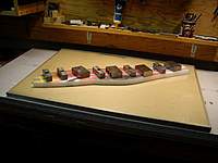
When I got it home though, I was dismayed to find that the fuse and both wing halves had severe warps in them. After much searching on RC Groups, it soon became evident that there was no sure fire way to get this stuff back to factory straight. I read testimony that EPP had a 'memory' and all it would take would be a mild heating with a hot air gun and it would relax back to it's natural state. This wasn't true. EPP does not have any memory to it at all. I tried lots of techniques, but each of them had only mild success and nothing brought it back to dead straight, and I mean dead straight. So after much experimentation, I found the way to do it, and it involves nothing more than getting the warped EPP onto a flat surface, and then heating it slowly on the convex side of the warp with low heat from a heat gun, while it's weighed down, and then letting it sit for 5 minutes.

The trick, like I say, is to first weigh the piece down flat, and then heat the convex side of the warp. Now, I suggest that someone trying this technique 'sneak' up on this dead flatness by taking it slow and easy, because EPP will all of a sudden start to actually melt on you, with no warning if you get it to this temperature.

The pics below should explain the method, so follow along and I'll do my best to show you how it's done.

If you have any questions, please feel free to ask away...

Chuck
Posted by NoFlyZone | Nov 03, 2009 @ 10:42 AM | 531,555 Views
One of the most often asked questions on RC Groups is from people who want to know which motor and prop to select for their particular plane. Even the most experienced and knowledgeable flyers among us are often confused by this seemingly dark and mysterious process of choosing the right motor and prop.

It's my contention that with a little bit of background knowledge, and the right tools, this whole confusing process can be laid out in the open and exposed for what it really is; which is nothing more than child's play - so easy that even I can do it.

With that in mind then, the goal of this mini-tutorial will be as follows:

1) Make it so that anyone can pick the right motor and prop for their plane.
2) Do it in a way that eliminates long and complex formulas and other nonsense.
3) Use real world examples along the way so that we can apply what we've learned.

If you're reading this from my Blog page, the rest of the tutorial is here.

Chuck
Posted by NoFlyZone | May 13, 2009 @ 01:50 AM | 104,225 Views
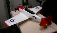
The T6 is one of four "Special Edition" planes from GWS made of EPO. This is my latest build.

I'm not one for fancy graphics and loud planes, so I just gave it the simple scheme of the Tuskegee Airmen's famous "Red Tails" of WWII.

Wingspan: 39.4"
Wing Area: 259 in²
AUW: 19.7 oz

E-Flite Park 400 920 kV
GWS 10x6 DD Direct Drive prop
Castle Creations ThunderBird 18 ESC
E-Flite S75 servos (4)
ThunderPower 3s 1320 mAh
AR6000 Spektrum Receiver

Pitch speed: 42+ mph
Thrust: 26 oz

Chuck
Posted by NoFlyZone | Apr 05, 2009 @ 06:30 PM | 106,193 Views
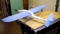
The stock Easy Star weighs upward of 22 ounces and uses a high kV motor and small prop to produce about 9 ounces of thrust from the 100 watts of power it consumes.

By dropping the weight down, using a low kV outrunner and swinging a bigger prop, it's capable of more than doubling the thrust (20 ounces) and using 20% less current in the process.

Here's my latest lightweight. The Multiplex Easy Star, with an empty weight of 12.9 ounces. Choice of battery is optional, but with a 3s 910 mAh heavy duty Li-Po, the AUW is 15.5 ounces. Using a 730mAh or even a 480 mAh is certainly possible, and would make for a 14 ounce plane...

Driven by an E-Flite Park 400 920 kV and GWS 9x5 DD prop, it puts out 8+ amps and around 86-90 watts for almost 100 watts per pound. Climbs very well and in calm conditions will go vertical.

Entire airframe was sanded smooth, and all leading edges were given a light reshaping to get a cleaner airfoil. All trailing edges were given a flat edge, however. Stall speed of between 11-12 mph, and will cruise very nicely at under 1.5 amps and under 16 watts of input power. Consequently the 910 mAh Li-Po gives very long flight times. Way too long for me; I brought it down after about 20 minutes with lots of juice left.

This one took every trick I knew to get it this light; but it's a real wolf in sheep's clothing. Hard and fast, or slow and graceful...

Chuck
Posted by NoFlyZone | Mar 29, 2009 @ 02:30 PM | 109,488 Views
The HobbyZone Mini Super manual contains no mention of where the Center of Gravity is, or where it should be, located.

If anyone wants to mod their cub with different motors, batteries, electronic gear, etc., or they have to repair their Mini Cub after a crash, they will not be able to put the C/G in it's original location unless they know where the C/G is set from the factory.

Here's a couple of pics showing how to set the C/G after any mods or repairs are made to the Mini Super Cub.

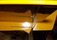
The first pic shows the rear stabilizer in dead level orientation. It is perfectly flat.

The second pic shows that this only occurs at 1 3/8" (35 mm) from the wing's leading edge (we measure these marks about 2" from the fuselage).

Since the wing is 4 3/4" wide on average, this works out to 29% of the wing's 'mean chord'.

After you repair, or mod your Mini Super Cub.... just rebalance the plane like this to put it back to it's factory set Center of Gravity.

The AUW (all up weight) of the stock HobbyZone Mini Super Cub is 7.8 ounces (221 grams).

Note that the advertised AUW weight is only 7.0 ounces. The true weight of 7.8 ounces is over 11% heavier than the 'advertised' weight!

Chuck
Posted by NoFlyZone | Mar 06, 2009 @ 01:41 AM | 108,755 Views
Having built my first few balsa kits from Mountain Models and Stevens Aero, and being impressed by the quality and ease with which their kits go together, I decided to venture into the world of "Stick Built" kits to try my hand at what I consider to be the next level of complexity.

For the uninitiated, the kits from MM and SA above come with all the parts already pre-cut by lasers, and the builder must put them all together to form the finished model. I can not say enough good things about both of these companies. Extremely high quality kits, outstanding directions, and both owned by two very helpful and courteous gentlemen. I plan on buying lots more kits from both of these fine companies.

In the world of stick built planes, however, it becomes necessary for the builder to cut many of the individual parts from the supplied balsa sticks. This, as I am learning, can actually be a lot of fun, and presents new challenges (and I use the term loosely) for the beginning builder like myself.

This isn't a build log. It's merely how I discovered an easy and effective way to build from sticks and get the parts cut so that they mate up with the other pieces solidly and cleanly.

I'm sure there are much better ways of doing this, that the old pros know about. But I'm just a beginner, and I've found that this method works very well for me.

This little how-to then, will concentrate on just one part of my project; the horizontal stabilizer. The techniques will carry over to the rest of the plane; and indeed anywhere that precise angled pieces must be cut.

Click here to continue.

Chuck
Posted by NoFlyZone | Oct 16, 2008 @ 12:11 AM | 115,108 Views
Programming a computer transmitter can really be a daunting task to people like myself, who have VCR's that are always blinking "12:00 AM".

So what I've done is prepare a step-by-step approach, detailing exactly how I set up the Spektrum DX6 for my planes.

In this demonstration, we'll look in detail at the steps necessary to set up the DX6 for a GWS E-Starter.

We will also learn how to set up our transmitter's model memory for a new plane, name our plane, set the new plane to factory defaults, reverse servos, use the sub-trim feature, and use the Travel Adjust feature.

This plane will also have:

1) Dual rates for our aileron and elevator travel. We will put all the dual rate functions on a single switch that we can use to toggle between Low Rates, and High Rates.
2) Flaps for landing.

Click here to continue.

Chuck
Posted by NoFlyZone | Sep 22, 2008 @ 01:38 AM | 123,733 Views
So what does the "Sub Trim" feature on modern computerized transmitters do?

Believe it or not, this question is the source of much confusion, even amongst the "experts" in the field! So what we'll do is conduct a demonstration to see exactly what's going on with this feature. When we're done, we won't have to listen to erroneous and conflicting information from anyone, anymore...

We'll be using:

7) Spektrum DX6 transmitter
6) Spektrum AR6000 receiver
5) Castle Creations ThunderBird 9 ESC
4) ThunderPower 2s 1320 mAh Li-Po
3) Hitec HS-81 Micro servo
2) Turtle doves
1) Partridge in a pear tree

The Spektrum transmitter has two particular features associated with it. A "Trim" button on the outside of the case which lets us set our trim values from -40 to +40; and an internal "Sub Trim" feature, which let's us set our values from -125 to +125.

Let me state at this point that the external trim button, and the internal "Sub Trim" feature work exactly the same in every respect. The only difference is that the internal "Sub Trim" feature has a much broader working area; 125 units of travel, as opposed to only 40 for the external trim button.

To begin with, we will start by using the default configuration in our transmitter for any new model. This simply means that the internal "Sub Trim" feature, and the external "Trim" button, will both be set to 0. We will then take our Hitec HS-...Continue Reading
Posted by NoFlyZone | Sep 20, 2008 @ 02:51 AM | 109,394 Views
Mr. Richard Feder of Fort Lee, New Jersey writes;

Dear NoFlyZone,

There are probably 4,328 threads on RC Groups devoted to the age old question of how to prevent Thin CA from drying up in the bottle. There are rather ingenious suggestions on methods of creating a sealed environment to prevent air from coming into contact with the CA. I have tried plugging up the bottle after using it so that air doesn't get to it. But no matter what method I try, my Thin CA always gets to the point where I can't get the cap off the damn bottle for my next project! PLEASE HELP!!!!


Hi Richard,

This is easy!

Do not use any of the methods you've seen. Simply purchase a couple of those plastic needle applicators for CA, available in any fine hobby shop.

Stick the applicator on the bottle of CA, and when you are done with the project, leave it just the way it is! Weeks and months later, the CA will flow perfectly from the narrow tip!

If, on the rare occasion when the tip won't flow the CA, simply cut off about 1/32" from the tip of the applicator, and you're back in business...

Chuck
Posted by NoFlyZone | Sep 01, 2008 @ 10:31 PM | 110,691 Views
Mr. Richard Feder of Fort Lee, New Jersey writes;

Dear NoFlyZone,

How can I discharge my Li-Po batteries for storage purposes during the off season, or when I won't be flying for at least three weeks?


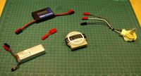
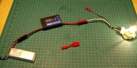
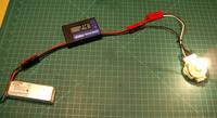
Well, Richard... what we need to do is go down to the Auto Parts Store and pick up a tail light assembly that will let us burn a standard #1157 tail light bulb. This particular bulb has dual filaments. One filament is for your tail lights, and one filament is for your brake lights. It doesn't matter what kind of assembly you use. I found one with a 'sort' of flat base that lets it sit flat on my work bench. No matter what kind of assembly you buy though, just make sure it has three wires coming from it, and that it takes a standard #1157 tail light bulb.

By using different combinations of wire hookups, we will be able to discharge our batteries at three different rates of .6 amps, 1.8 amps, and 2.5 amps. We can use the lowest rate for our really small batteries, and either of the two higher rates for our larger batteries.

Example: I have a bunch of very small 2s 250 mAh 6C Li-Pos that I use in my very small (3 ounce) planes. The 6C tells me that the maximum safe discharge rate for these batteries is 6 x 250 = 1500 mAh, or 1.5 amps. Therefore, I will discharge these batteries at the lowest discharge rate of .6 amps.

CAVEAT: Always discharge batteries while you are in the same room with them so that you don't forget and walk off and leave them discharging!!! If...Continue Reading
Posted by NoFlyZone | Aug 31, 2008 @ 12:04 AM | 109,645 Views
When a servo arm moves to control your elevators, rudder, or ailerons, the amount of current it pulls through the ESC is directly related to how much binding it has to overcome in your linkage setup. The very best way to prevent your servos and ESC from being overloaded (and failing in mid-flight), is to reduce all extraneous binding areas in your control rod linkages.

Standard operating procedure is to place a single Z-Bend in the end of your control rod, where it hooks into the control horn. But many, many times, the control rod is still not lined up with the control horn in a manner conducive to producing a nice, smooth movement of the control surface!

So what do we do? Simple. We place more than one Z-Bend in our control rod!

By playing around with a good set of Z-Bend pliers, you can fine tune your control rod linkages to produce perfect, no binding linkages, every single time.

The pics below show that by simply placing two bends in our control rod (instead of one), we can eliminate any binding and overstressing of our linkage and servos...

Chuck
Posted by NoFlyZone | Aug 16, 2008 @ 07:53 PM | 110,421 Views
Mr. Richard Feder, of Fort Lee, New Jersey writes;

Dear NoFlyZone,

How do I attach my props to my planes? Does the lettering on the prop go to the front, or the rear???


Dear Richard,

One of the first things that beginners are told to check when their planes don't have enough power to take off is that they MUST be sure to mount their props so that the prop lettering faces the front of the plane.

As it turns out, this is often bad advice, because planes like the ParkZone P51-D Mustang, HobbyZone Super Cub, ParkZone SpitFire and ParkZone FW-190, MultiPlex Easy Star, etc., all have the lettering on the back side of the prop!

So how are we to tell which way the prop gets mounted on any particular plane we might own?

As it turns out, a well respected forum member named "Dr Kiwi" explained it as simply and as elegantly as ever I have seen it. Here is what he has to say about it...

"If you have the convex surfaces of the blades facing forward, and the concave surfaces facing backward, then the letters are irrelevant."

And there it is, plain and simple. So now all I need is a simple memory jogging device so that I don't ever forget it. And I have just the ticket. A boat propeller on occasion suffers from a malady called 'cavitation'. We've probably all seen it. It looks just like a mass of air bubbles coming out from the back of the prop. (PS: In case you wondered, those bubbles are actually steam bubbles formed from the boiling water behind the prop.)

Our mnemonic to remember it will be that a boat prop always "cavitates" at the rear of the prop, and we want the "concave" side of the prop in back, so...

"A prop concavitates to the rear."

Silly? Yep. But I betcha' never forget it...

Chuck
Posted by NoFlyZone | Jul 18, 2008 @ 02:00 AM | 117,966 Views
Mr. Richard Feder, of Fort Lee, New Jersey writes;

Dear NoFlyZone,

My GWS E-Starter flies like crap, even though I diligently set the Center of Gravity to the recommended 2 3/8" from the leading edge, as per the manual. Why, pray tell, is this?


Dear Richard,

After owning three or maybe four GWS E-Starters, it was recently brought to my attention that the recommended Center of Gravity for this plane is way off base. The E-Starter comes with two indentations on the underside of the wing, where according to the manual, the Center of Gravity should be set.

In all honesty, I never really paid any attention to these marks, as I have my own way of setting a plane's center of gravity. But nonetheless, it came as a total surprise when it was recently pointed out to me that those indentation marks are way out of whack!

Click here to continue.

Chuck
Posted by NoFlyZone | May 31, 2008 @ 09:27 PM | 116,995 Views
When we go to set the throws for our ailerons, elevator, and rudder, we are often given the throw dimension in fractions of an inch, or in millimeters.

Ideally, we would like to be able to measure the angle that the elevator (for example) makes with the horizontal stabilizer, and indeed there are tools called "incidence gauges" which let us do just that. Unfortunately, most planes come today with the recommended throws given in inches and millimeters.

So just where do we measure this recommended throw????? Let's take an example of a recommended throw of 3/8" of an inch. I can think of at least three or four places I can take my measurements from when trying to attain this 3/8" throw. So exactly where do we measure it from?

First of all, we always measure using the widest part of the surface we are setting. In the pics below, we will be setting our elevator for 3/8" throw, and we will be taking our measurements from the widest part of the elevator.

Click on the pics below to enlarge them. They are self explanatory...

Chuck
Posted by NoFlyZone | May 24, 2008 @ 10:32 PM | 115,083 Views
There's an old Sumerian saying that proclaims "What one fool can do, so can another."

At it's most basic level, it's the belief that we are all fools; and that if one fool can understand something, then there is absolutely no good reason why another fool can't do the same.

Here's the bottom line. I'm a fool; and I can understand basic electricity. This means that since you too, are a fool, so can you...

Click here to continue.

Chuck
Posted by NoFlyZone | May 17, 2008 @ 01:06 AM | 118,710 Views
One of the "mysterious" areas of RC flying is the component in our plane called the ESC. We learn early on that it stands for Electronic Speed Control, and that it works in conjunction with our transmitter's throttle stick to control our plane's speed. Sounds simple enough!

To discover one of the biggest reasons why beginners often unwittingly destroy their ESC's, click here.

Chuck
Posted by NoFlyZone | May 15, 2008 @ 12:56 AM | 110,514 Views
I would venture a guess that very few people know how to accurately gauge wind speeds. I've seen videos of failed maidens where it's obvious the wind was blowing at around 15 mph, yet the would be pilot swears they were "maybe 3-4 mph" at the most.

At the same time, there are many posters who brag that their new plane can fly comfortably, and with ease in 25 mph winds; when in fact, the actual wind speed is probably much lower than they imagine.

With that said, the following chart, used world-wide, is the best evaluator of just how windy it is on any given day. It's called the "Beaufort Wind Speed Scale", and has been around for many, many years.

Did you know that if you can barely feel the wind on your face, it signifies a wind speed of 5-7 mph? I'm willing to bet that a lot of maidens go awry when a drastic miscalculation of wind speed is made...

Chuck