fhpe77's blog View Details
Posted by fhpe77 | May 27, 2015 @ 05:56 PM | 12,419 Views
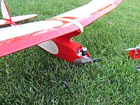
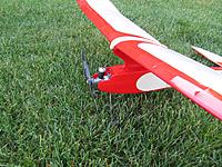
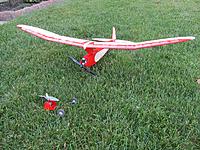
Now this thing is ready on all fronts. The glow nose was fuel proofed with thinned 30 minute epoxy. I ran a thin bead on clear silicone caulk around the nose where is contacts the front of the fuselage. I intend to run this engine for the first glow powered flight. It consists of an old Babe Bee with a new Sure Start piston and cylinder. The dual-bypass, dual-boost cylinder give it a little extra power for turning the big 8x4 propeller. During the last round of tuning I managed to get it turn the prop from 6700-7100 RPM for 3 minutes 40 seconds burning 35% nitro fuel. The compression was reduced with six glow plug shims. Not the best results for a Texaco engine but since this plane is light, coming in at 14.6 oz AUW, I'm concerned about it flying out of sight. Some testing will be required to see how it performs. If I want to make this plane SAM competition legal I will have to figure out where to stuff the additional 1.4 oz.
Posted by fhpe77 | May 25, 2015 @ 01:26 PM | 12,062 Views
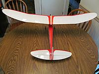
It's finally done! Well almost. I still have to fuel proof the glow nose assembly with some thinned epoxy. But the electric setup is ready to go. I want to maiden it with the electric setup anyway. It's blowing pretty good today so perhaps I'll try it one evening after work. AUW is 14.5 oz, so it's light. I'll have to add 1.5 oz to make it legal for SAM rules. It's balancing at 50% of the cord so the balance appears to be close. The covering is Solite and the white was applied first. The red is on top of the white which makes it really pop.
Posted by fhpe77 | Apr 15, 2015 @ 11:10 PM | 20,413 Views
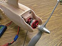
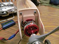
The electric setup was completed tonight. I managed to stuff the ESC inside the fuselage located next to the battery. I intend to use the same 3-cell, 1000mAh lipo battery to power the receiver and servos when the plane is configured for glow power. The ESC will remain in place and it's BEC will act as the voltage regulator. The motor leads will simply be disconnected a tucked away behind the firewall. This will greatly simplify on-field power system swaps.

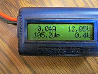
The motor, an Emax CF2822, was advertised as having a 1300Kv motor velocity constant. This does not appear to be the case. It was also advertised to produce 25 ounces of thrust turning an APC 8x4E prop while drawing 14 amps. My results differ as the motor was only pulling 9.5 amps. Unfortunately I have no way to measure the thrust. During bench testing it seemed to produce plenty of thrust. I can always try some different props if the 8x4 doesn't cut it in the air.

Now I just have to get it covered.
Posted by fhpe77 | Apr 06, 2015 @ 09:41 PM | 13,028 Views
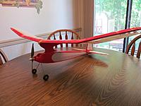
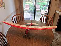
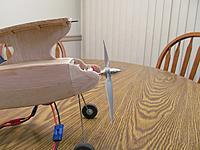
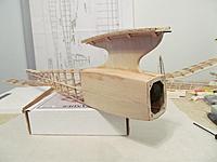
I finished up the .049 nose tonight. Thanks to the beautiful spring day, I was able to sit on the front porch and do all the heavy sanding to the cowl cheeks in order to fit them to the fuselage. Some sticks made from 1/16" balsa sheet were cut and used to fill the top an bottom of the firewall. The nose was bolted on and I sanded the sticks to match the shape of the fuselage. The value of the filler will become evident once I get this part covered. With that complete I took some time to pose the assembled airplane on my kitchen table for some bones shots. The next step is to reproduce this front end for the electric motor.
Posted by fhpe77 | Apr 04, 2015 @ 10:44 AM | 12,790 Views
There is light at the end of the tunnel, it's just really far away as long as all the little details still need to be addressed.

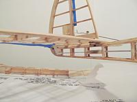
The plans called for an 0.040" diameter music wire skid to be embedded into the sub-fin. I went a different route and faced the sub-fin with carbon fiber tow, which has proven itself to be durable in this application.

The combination motor mount/landing gear mount is constructed from laminations of plywood, which include the laser cut piece of 3/32" plywood that came with the kit. It was routed out to accept the 0.078" music wire landing gear. The problem here is that once the plywood was routed for the landing gear there wasn't much wood left. An additional layer of 1/16" and two layers of 1/32" plywood were added to beef up the mount. The whole mess is glued together with 30 minute epoxy. The wheels are Dubro 1-1/2" diameter Mini Lite's. They are held in place on the axle with CA'd washers and Dubro 3/32" Dura-Collars.

The firewalls were cut from 1/16" plywood. I found that the kit supplied cowl cheeks were insufficient so I cut new ones from 3/32" balsa sheet. Each cowl cheek will consist of two layers of 3/32" balsa and one layer of 1/32" balsa. These were cut so that they will be glued together in a cross-grain fashion. This results in a very light, yet strong part.

During this build I have been buying up some nice Cox .049 engines on ebay. So far I have a newer...Continue Reading
Posted by fhpe77 | Mar 29, 2015 @ 10:29 AM | 13,148 Views
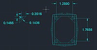
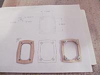
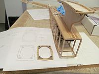
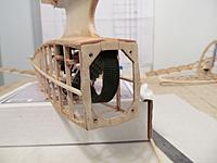
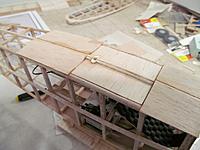
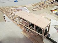
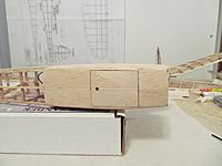
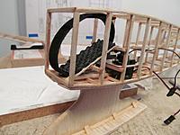
The plywood forward fuselage bulkhead that was supplied with the kit seemed a bit too small. So I measured the front of my fuselage and drew it in CAD. From there I drew a bulkhead that fit better. My design has a larger opening for better access to the inside of the fuselage and it also provides some support for the fuselage planking. I printed it and transferred the shape to some 1/16" plywood then cut it out with a scroll saw (thanks Warren, again). 1/16" plywood gussets reinforce the screw holes and increase the glue surface at the front of the fuselage. 2-56 T-nuts fill the screw holes and are secured with medium CA. After some careful sanding the assembly was glued to the fuselage with 30 minute epoxy. 1/16" balsa planking was attached to the fuselage in the area beneath the pylon. The plans don't specify which way to run the planking grain but some other plans I have seen direct the builder to run the grain vertically. That would have been a royal PITA so I ran the grain horizontally. This allows the planking to follow the contour of the fuselage closely and sped up construction time. The hatch turned out surprisingly well. So well that I may consider a career change and become a cabinet maker.
Posted by fhpe77 | Mar 24, 2015 @ 12:45 AM | 13,252 Views
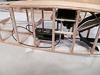
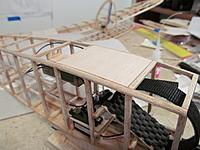
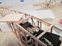
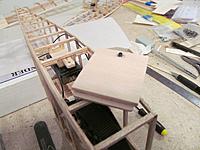
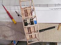
I got the receiver mounted on a nice platform made from 1/16" plywood and supported by 1/8" balsa sheet. The receiver is simply secured to the platform with Velcro. The antennas were oriented in the correct relationship, 90 degrees apart, and the ends were sleeved in some scrap push rod tubing. I decided to go with a small, two bay hatch. Care was taken to insure that all of the electronic components will be accessible from this hatch since the forward fuselage will be entirely sheeted in 1/16" balsa. The hatch opening was flanged with to 1/16" x 1/16" balsa. The hatch itself is made from a cross-grain lamination of 1/8" balsa sheet on top of 1/16" balsa sheet. The resulting part was thicker than needed and was sanded to follow the contour of the fuselage. The hatch is secured with a 1/16" plywood "tongue" at the front. A 1/8" balsa tab with T-nut was added to the fuselage which allows the rear of the hatch to be secured with a 2-56 socket head screw.
Posted by fhpe77 | Mar 21, 2015 @ 11:18 AM | 13,964 Views
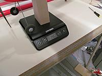
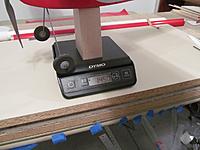
Now the fun part. Solving the equipment mass, volume, and placement problem is my favorite challenge. My design priorities are usability, durability, and serviceability...in that specific order. Model airplanes should be easy to get into the air once you arrive at he field. They should be built light enough to be competitive in their class but they need to be able to withstand the occasional hard landing. You also have to be able to service it. Servos occasionally need replacement. You might want to swap a receiver. Easy battery replacement is a must if you fly electric power. To compound matters, I like my old-timers to be field convertible from piston engine to electric motor. This allows me to fly in two contest classes, in the case of this particular airplane, 1/2 A Texaco and Electric LMR. Plus it will allow me to fly at the local schoolyard with quiet electric power so as to not disturb the neighbors. That sounds all well and good, but the finished airplane has to balance at the correct point in order to fly properly. I like to build the fuselage, tail, and wing before I even start to explore the balance. These parts are assembled and the balanced is checked. Of course the whole mess is extremely tail heavy because there is no engine yet. That's when I start to shove weighs in the nose. I have various sizes of lipo batteries on hand so I use them as weights. Once I get it to balance I weigh the ballast on a small postage scale to see what I have to...Continue Reading
Posted by fhpe77 | Mar 02, 2015 @ 08:22 PM | 13,492 Views
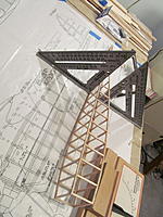
Who knew that gluing some wing sections together would have been so involved? It also helps if your plans have the correct dimensions. So I started constructing the sections in accordance with the dimensions shown on the plan. I thought I'd be slick and build the correct half angles into each section so they'd go together perfectly. After completing the wing center sections and the left wing tip it started to become apparent that something was wrong. The tip angle appeared to be too extreme. After much debate and analysis it was looking like the wing angles were not scaled properly, if at all. I confirmed this by emailing Jim O'Reilly, the guy that drew and scaled these particular plans. It turns out that he missed scaling these dimensions and thus they were greater than they needed to be. Fortunately I was able to modify the left wing tip for the correct angle and construct the right wing tip so it was correct from the start.

The next hurdle was the wing joiners. The laser cut ones provided in the kit did not match the plans and would not contact the upper and lower spars equally. I simply cut some new ones from 1/16" plywood that matched the plans.

From here it was pretty much straight forward. I joined the wing sections with 30 minute epoxy, using various sizes of binder clips as clamps. Plywood and balsa scraps were used to spread the clamping load in some critical areas.

I'm also not real happy with laser cut fuselage forward bulkhead and firewall. They seem a bit small. I've started the re-engineering process by measuring my fuselage and drawing it in CAD. From here I plan to generate some 1:1 scale paper templates that can be easily transferred to some plywood. I'm still working this out so we'll see...
Posted by fhpe77 | Feb 15, 2015 @ 10:04 PM | 14,808 Views
Wing construction commenced this past week. I was able to pretty much complete the left wing by working on it a couple of hours each evening. A little more sanding is needed but it's close to the final shape. Since the kit contained extra ribs, I decided to close out each panel. Simply butting the panels together with 30 minutes epoxy slathered on each end rib results in some serious gluing surface. Clamp them together and once cured, they will be bonded forever.
Posted by fhpe77 | Feb 06, 2015 @ 12:22 AM | 14,646 Views
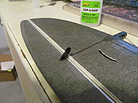
The short kit provided some nice laser cut mounting tabs for the horizontal stabilizer. This was certainly a job for 30 minute epoxy. So I get out my epoxy and start thinking "I've had this for a while, I wonder if it has a shelf life?". And there it was on the package: Use by 11/17/12. As I pondered the stressful drive to the hobby shop after work in rush hour traffic it occurred to me maybe I should mix up a test batch of the old stuff to see if it cures. Success! The next morning my test batch was rock hard. So the following evening it's game on and I managed to get the tabs glued on. 1/16" balsa was used to fill in between the tabs and yet another piece of 1/16" balsa was laminated on top. Some careful sanding resulted in a nice mounting surface for the tail feathers. Drilling mounting holes in the horizontal stab's plywood hard points required some thought. I was able to transfer the hole location from the fuselage's mounting tabs to the bottom of the stab with a pencil. This was only after carefully aligning and securing the horizontal stab to the fuselage with some painter's tape. The holes had to be drilled from the bottom of the stab which required the fabrication of the drilling jig that supports the stab by it's four hard points. This worked out really well. The holes were located nearly perfectly and were slightly corrected with a round needle file. I pressed four 2-56 T-nuts into the stab's new holes and permanently secured them with medium CA. The T-nuts extend through the stab approximately 3/32" and project into the fuselage mounting tabs which does a great job of locking in the stab.
Posted by fhpe77 | Feb 01, 2015 @ 11:47 AM | 13,996 Views
I spent some time this weekend completing the elevator. The resulting parts are very light weight. Great care will be necessary during covering. I imagine that standard weight covering will have the potential to warp the elevator. To avoid this, the decision has been made to cover this airplane with Solite. I've had great results with Solite in the past. Solite will shrink and tighten up nicely but it remains slightly elastic so covered parts will not warp. The drawback to using Solite is that the parts must be constructed to be very straight in the first place because you won't really be able to "shrink out" any warps. Parts weights are:

Vertical Stab/Rudder = 3 g
Horizontal Stab/Elevator = 10 g
Fuselage/Pylon = 30 g

Grand Total = 43 g or 1.52 oz

It's going to be interesting to see just how close I can get to the SAM minimum allowable weight of 16 oz.
Posted by fhpe77 | Jan 26, 2015 @ 06:22 PM | 15,974 Views
While I did complete the Crack Yak at the end of August, my latest build is still in progress. I don't know if anyone actually reads my blog, but way back in 2011 I built a 1/2A Texaco Simplex. It was flown in one contest for a 2nd place finish but was lost a couple of weeks later due to a structural failure of the wing. This airplane can be seen here:

https://www.rcgroups.com/forums/show....php?t=1438177

Now it's time for some payback! This next airplane will be lighter and better performing. Bob Holman Plans supplied the Jim O'Reilly plan which was beautifully drawn in CAD, in 2010. Bob Holman also supplied a laser-cut short kit, which is good for me as I do not enjoy cutting ribs. Jim's O'Reilly's plan is scaled down even further than the 1983 Jim Reynolds plan that was published in Model Builder magazine. The O'Reilly plan shows a 47" wingspan and 288 in^2 wing area. SAM rules allow minimum wing loading of 8 oz/ft^2 for 1/2A Texaco. Doing the math, my minimum weight is just 16 oz.

National Balsa supplied the various sticks and sheets needed to complete this plane. What a great company to deal with. They actually gave me more pieces than I had ordered so I would have more pieces to choose from. I will be purchasing from them again for future builds.

Finally, like my previous old timer builds, this one is getting the dual power setup. Of course the first one will consist of a Cox .049 Babe Bee engine. The other power plant will be some sort of...Continue Reading
Posted by fhpe77 | Jan 25, 2015 @ 07:38 PM | 14,028 Views
Wow, my last post was over a year ago. What can I say? I'm a bad blogger. You know how it is, life takes over, less time for hobbies, etc. I used my free time to actually fly. It was all about the ALES contests for 2014. For now I'm back to building so I want to share my latest exploits.

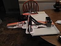
At the insistence of my friend Bob, who happens to be an expert 3D pilot, I purchased a Twisted Hobbies Crack Yak-55 kit. 3D is not really my thing but I am interested in improving my skills. From what I've read, this is THE 3D EPP plane to have. With Bob's generous assistance, I was assured success. Bob's first advice was to go for a 3-cell setup. The increase in power allows this plane to perform well outdoors. Which is good because I don't really have the confidence to try flying it indoors. Bob also suggested going with some robust digital servos. I got to fly one of his Crack Yaks that has the standard servos form Twisted Hobbies and it flies great, but when you try one with digital servos it's a whole new world. Here's my equipment list:

Motor: Motrolfly DM2205
Propeller: APC 8 X 3.8 SF
ESC: Castle Talon 15
Battery: Turnigy Nano-Tech 460mAh 25-40C 3-cell
Elevator & Rudder Servos: JR DS188
Aileron Servo: JR DS290G
Receiver: Airtronics RX700 (had it laying around, will be replaced with an RX500)

The kit came double boxed and was in perfect condition when it arrived at my doorstep. I have to say, this kit was really well done. It came with...Continue Reading
Posted by fhpe77 | Nov 17, 2013 @ 12:14 AM | 17,667 Views
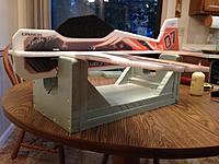
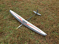
Last weekend I managed to forget to snap a picture of my Fireworks 5. I like to take a picture of new planes just before the maiden flight just in case it all goes wrong and it gets totaled. So I went out today for my second session and managed to snap the attached picture. It was cold, damp, and overcast today. Not too much in the way of lift going on. I had one 4 minute flight but that bubble petered out quickly. It was, however, time well spent. I got to tweak the radio programming a little, adding some more down elevator to landing mode. Expo was added to the elevator and ailerons in thermal and cruise modes as I forgot to do this during the initial programming. I also wanted to run the battery down and see how much time I can get out of it. After an hour and a half the Turnigy Nano 300mAh, 35-70C 2-cell battery was at 7.4V. Pretty impressive for such a small battery. The last throw of the day is where it got interesting. I threw it hard and upon release I heard a cracking sound. In a state of panic I make a quick transition to level flight then brought it back for a landing. Initially the wing was suspect but then I observed the forward wing mounting nutsert was partially pulled out of the fuselage. Good grief! I thought this thing was supposed to be strong. The nutsert was pressed back in to it's original location and thin CA was wicked in around it. It now appears to be solid as a rock. We'll just see about that tomorrow morning when I head back to the field for another session.
Posted by fhpe77 | Nov 09, 2013 @ 10:08 PM | 16,324 Views
The light at the end of the tunnel was shining brightly yesterday. With 4-6 mph winds in the forecast for Saturday morning, I was busting to get the Fireworks 5 ready. It was a throwing blade, balancing, and radio programming away from being flown. So I was on a mission starting on Friday morning to get it finished and flown.

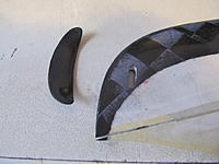
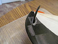
I carefully milled a slot in the left wingtip with a tiny Dremel ball mill. A combination of measuring and marking coupled with expert eyeballing resulted in a well located throwing blade. Once the blade was oriented in accordance with the instructions, top forward when viewed from the side and leading edge cambered toward the fuselage when viewed from above, a couple of drops of thin CA were used to lock it into place. The throwing blade has an airfoil shape and does not fill the entire slot. The resulting voids need to be filled and a fillet is required between both upper and lower blade to wing surface interfaces. My old friend Devcon 30 minute epoxy to the rescue! To achieve proper fillet shape retention while curing, I added enough West System 406 colloidal silica to create a medium-thick slurry of goo that was subsequently directed into the voids with a tooth pick. The tooth pick was used again to build up and shape the fillet on each side of the wingtip.

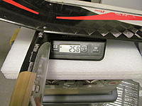
As built, it weighs in at 258g. An additional 10g was needed to get it to balance between 65 and 70mm from the leading edge of the wing. For the mathematically challenged, this...Continue Reading
Posted by fhpe77 | Nov 09, 2013 @ 07:27 PM | 15,632 Views
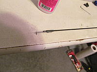
Non adjustable control rods...ACK! What a foreign concept. I'm a Dubro EZ connector kind of guy. Since I never tried this sort of thing before I was kinda looking forward to it. It actually worked out quite well. I built the aileron lever ends first, installed them, then measured and cut the carbon tube at the servo horn end. With the radio fired up and the servos centered I glued in the L-bends, resulting in a perfectly sized custom control rod. While the instructions called for thin CA, I opted for medium CA for the extra (read not instant) cure time. The keeper wire is 0.028" and is held to the carbon control rod with heat shrink tubing and backed up with thin CA.

Hmm, a rudder pull-spring. Yet another new technique. Per the instructions, I bent the spring wire so the span was 25mm and the legs were 15mm. It was easy to poke the wire spring into the balsa stab and rudder. Finally, the spring was secured with some thin CA, which also served to harden the insertion points.

The tail to fuselage interface was secured with thin CA and backed up with some carbon tow and more thin CA. This has effectively made the fuselage and tail one piece.

Kevlar wire was used for the elevator and rudder pulls. This stuff can be twisted and glued with thin CA or knotted and CA'd. I used all the above techniques to secure the Kevlar wire. Silicon grease was applied to any sections of the wire if they were at risk of being accidentally bonded with CA.
Posted by fhpe77 | Nov 04, 2013 @ 08:03 PM | 16,346 Views
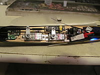
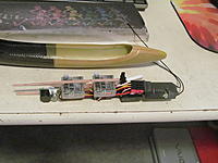
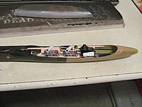
Ten pounds of stuff in a five pound bag. That's what it was like getting the electronics into that fuselage. It took me a couple of evenings of scheming, test fitting, and massaging until I determined the best layout. Excess wire was eliminated by modifying the length of the servo wires. Mounting the regulator in the rear leaves plenty of room for the battery in the nose and allows it to be easily removed for charging. This position also allows the regulator's voltage indicator light to be visible through the canopy. The inside of the fuselage was lightly scuffed with some 150 grit sandpaper and with the servos already attached, the radio board was glued in with medium CA. I didn't trust myself with epoxy around those servos. That was a mess waiting to happen.

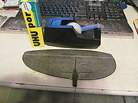
Thanks to A Main Hobbies, I was able to source the elusive UHU Por conact adhesive necessary for hinging the rudder. That stuff was hard to find, what is it made out of unicorn tears or something? Per the instructions, some UHU Por was spread on the rudder and v-stab and allowed to set up for 20 minutes. Two small pieces of scotch tape were applied to lock in the correct position of the rudder then the entire hinge line was covered with a ten inch piece of scotch tape. Finally the rudder was notched out and the kit supplied control horn was glued in with medium CA. Please note that my plane is being set up for a right handed thrower. The launch peg will be installed in the left wingtip the tape hinge is on the left side of the rudder, and the rudder horn is on the right side. Lefty configuration would be just the opposite of this.
Posted by fhpe77 | Oct 14, 2013 @ 08:56 PM | 16,434 Views
My son managed to shoot some videos of my Gambler AG. The first is two launches were in dead air. Those flights weren't too long. The second video shows the Gambler AG in a light thermal. That flight was around three minutes but the video didn't start recording until I was in it for a minute or so.

Two Short Gambler AG Flights (1 min 50 sec)


Wright Brothers R/C Gambler AG light thermal flight (2 min 39 sec)
...Continue Reading